Installation of Fiber Optic Cable:
Because of their light weight and flexibility, fiber cables are in most cases easier to install than their copper counterparts. There are some concerns, however, that must be faced by the individuals involved in designing the Installation of Fiber Optic Cable, for example, minimum bend radius and maximum tensile strength. The specifications for minimum bend and tensile strength are provided by manufacturers in their specifications and should be adhered to strictly.
First, some terms used in the fiber industry should be defined. A splice is a device or a process used to permanently connect fibers. A connector is a device used to allow cables to be joined and dis joined.
The basic and common requirements for splices and connectors are low loss (attenuation) and accurate alignment. A splice can be used to extend cable length or repair a break. A connector is used to connect the fiber cable to equipment, a junction box, and so forth.
Splices:
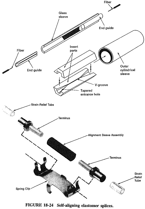
There are two basic types of splices fusion and mechanical. The fusion splice requires expensive equipment and controlled conditions. Because of adverse conditions, field service repair splicing is more suited for the mechanical splicing process (see Figure 18-24). The fusion splice requires expensive equipment (thousands of dollars) and is not suited for use under field conditions, for example, in trenches, manholes, or cables suspended from poles. The small power loss of the fusion splice (0.01 dB or less) and its overall reliability make it the choice for new indoor Installation of Fiber Optic Cable. The steps involved in making this splice are as follows:
-
By mechanical or chemical methods, clean all coatings from fiber (except for the cladding).
-
Scratch the fiber with a diamond scribe to induce a clean square break (this process is called cleaving).
-
Place the fibers to be spliced into the alignment assembly; inspect, them with a microscope for accurate alignment; fuse the fibers with an electric arc; and reinspect the fibers with a microscope.
-
Reinstall protective coatings according to the manufacturer’s specifications.
-
Test the splice optically for attenuation losses.
The mechanical splice is more suited for field service repair where conditions are unfavorable for using expensive bulky equipment. It is accomplished as follows:
-
Disassemble the mechanical connector assembly.
-
Insert the fiber, coated with indexing gel, into the holder alignment assembly.
-
Reassemble and test for attenuation (see Figure 18-24).
This type of splice will introduce an attenuation loss of 0.1 dB or less, which is reasonable.
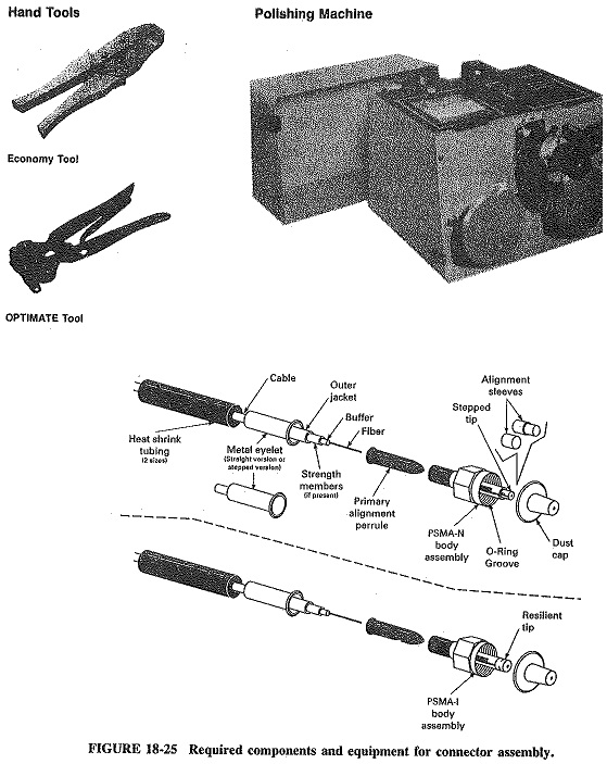
The process of preparing an optical fiber connector is almost as simple as that used for the mechanical splice, but it requires more elaborate equipment for polishing the fiber end and curing the epoxy protective coating. The steps are as follows:
-
Cleave the fiber with the cutting tool recommended by the manufacturer (see Figure 18-25).
-
Polish the end of the fiber in the connector assembly.
-
Place the fiber in the connector assembly (see Figure 18-25).
-
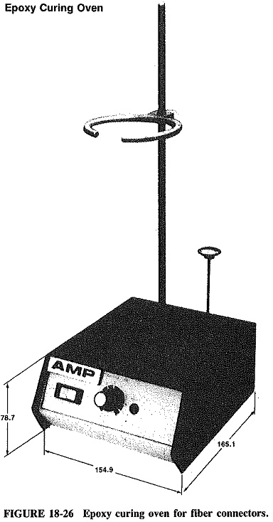
Reassemble with epoxy protective coating if necessary and place in the curing oven for the recommended time period (see Figure 18-26).
Because of the variety of situations encountered in the Installation of Fiber Optic Cable of fiber-linked communications and data handling systems, there are many different types of connectors and associated assemblies.