Microprocessor Based Protection Relay:
Reliable and accurate protection schemes are required for any system. Microprocessors can fulfill these requirements without fail. In addition to the system protection, microprocessors can perform all control operations, analysis as well as measurement. The cost of a protective scheme should be about 1% of the cost of the equipment to be protected. When the microprocessor is used to control the system in addition to system protection, it will be very economical. Presently, Microprocessor Based Protection Relay schemes are developed. Therefore, microprocessor applications will result in availability of faster, more accurate and reliable relays than conventional relays. These relays are known as static relays. A microprocessor increases the flexibility of static relays due to its programmable approach. A number of desired characteristics such as overvoltage, undervoltage, overcurrent, directional, impedance, reactance, and mho can be used in microprocessor-based relays. In this section, microprocessor-based overvoltage protection has been discussed.
Overvoltage Protection
Electrical appliances or any electrical and electronics instruments always require protection against over and undervoltage. The conventional relays are already used for the under and overvoltage, and the maximum and minimum level of voltages are not changeable. Though a micro-processor-based system is of high cost, but the advantage of this system is that the same system may provide protection against maximum and minimum allowable current and voltage with a scope to adjust maximum and minimum limits.
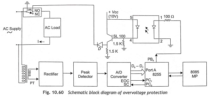
The schematic block diagram of the system overvoltage protection is shown in Fig. 10.60. It is depicted in Fig. 10.60 that a single-phase ac supply is connected to a load (electrical appliance) through an electromagnetic relay. This electrical appliance must be protected from overvoltage as well as undervoltage. For this, a Potential Transformer (PT) has been used to collect the voltage signal. The output of PT is fed to the input of a peak detector circuit to detect the peak value of the voltage. The output of a peak detector circuit is applied to the A/D converter for analog-to-digital conversion. For protection against over and undervoltage, an optocoupler circuit, MCT2E is used to connect to the pin PB0 of the I/O port. A 5 V dc supply has been connected to the opto-coupler circuit and the output has been connected to the energizing coil of an electromagnetic relay through a diode IN 4007.
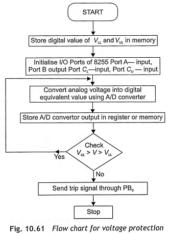
In Microprocessor Based Protection Relay, initially the upper and lower limiting values of voltage are stored in memory. Initialize Port A and Port C upper as input ports and Port B and Port C lower as output ports. The microprocessor receives the output of the A/D converter and compares the same with the upper and lower limiting values of voltage (VUL and VLL). Within the safe limit, the microprocessor sends signals 0 through PB0 and relay is OFF and supply current flows through load. If voltage value is either less than VLL or greater than VUL, the microprocessor sends ‘1 ‘ signal through PB0 and the relay coil is energized. As the relay becomes ON, supply voltage is disconnected from the system and the system will be protected. The flowchart of the program is given in Fig. 10.61.