Microprocessor Based Traffic Light Control:
Nowadays microprocessors are used to implement the traffic control system. Figure 10.62 shows the simple model of Microprocessor Based Traffic Light Control.
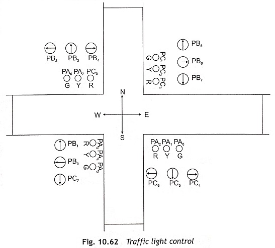
The various control signals such as red, green, orange, forward arrow, right arrow and left arrow are used in this scheme. The forward, right and left arrows are used to indicate forward, right and left movement respectively. The red (R) signal is used to stop the traffic in the required lane and the yellow (Y) signal is used as standby, which indicates that the traffic must wait for the next signal. The green (G) light for a particular lane remains ON for DELAY-1 seconds followed by the standby signal for DELAY-2 seconds. However, at a time for 3 out of the four roads, the left signal or the left arrow remains on even though that lane may have a red signal. The traffic light control is implemented using the 8085 microprocessor kit having 8255 on board and the interfacing circuit is illustrated in Fig. 10.63.
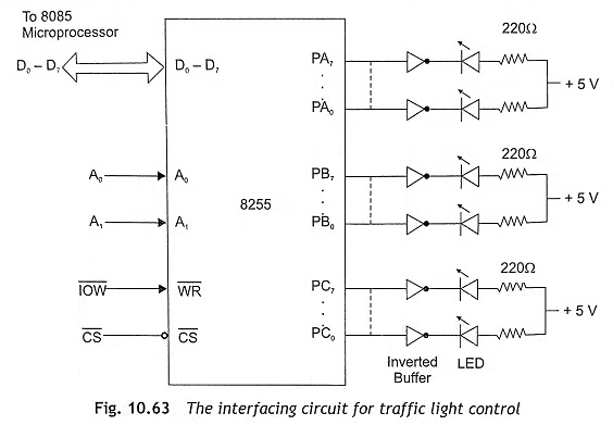
Each signal is controlled by a separate pin of I/O ports. The total number of logic signals required for this arrangement is twenty-four. The programmable peripheral interface device 8255 is used to interface these 24 logic signals with the lamps. The logic ‘0’ and ‘1’ represent the state of the lamp. Logic ‘1’ represents ON and ‘0’ represents OFF. All ports of 8255 are used as output ports. The control word to make all ports as output ports for Mode 0 operation is 80H. The traffic light control program can be written by the flowing steps:
Step 1 Initialize all ports of the 8255 as output ports.
Step 2 Determine the required status of Port A, Port B and Port C of 8255 for north to south traffic movement. Load data into accumulator and send to Port A, Port B and Port C for north to south traffic movement.
Step 3 Call delay subroutine -1.
Step 4 Before starting east to west traffic movement, north to south traffic movement will be ready to stop, and east to west traffic must be ready for movement. Therefore, determine the required status of Port A, Port B and Port C for this operation. Then load data into accumulator and send to Port A, Port B and Port C for north to south traffic movement which will be ready to stop and east to west traffic must be ready for movement.
Step 5 Call delay subroutine-2.
Step 6 For east to west traffic movement, determine the required status of Port A, Port B and Port C of 8255. Load data into accumulator and send to Port A, Port B and Port C for east to west traffic movement.
Step 7 Call delay subroutine-1.
Step 8 Prior to starting south to north traffic movement, east to west traffic will be ready to stop, and south to north traffic must be ready for movement. For this operation, determine the status of Port A, Port B and Port C of 8255. Load required data into accumulator and send to Port A, Port B and Port C for east to west traffic will be ready to stop and south to north traffic must be ready for movement.
Step 9 Call delay subroutine-2.
Step 10 Determine the status of Port A, Port B and Port C for south to north traffic movement. Load required data into accumulator and send to Port A, Port B and Port C for south to north movement.
Step 11 Call delay subroutine-1.
Step 12 Before starting west to east traffic movement, south to north traffic movement will be ready to stop and west to cast traffic must he ready for movement. Find out the status of Port A, Port B and Port C for this operation. Load required data into accumulator and send to Port A, Port B and Port C for south to north traffic movement which will be ready to stop and west to east traffic must be ready for movement.
Step 13 Call delay subroutine-2.
Step 14 For west to east traffic movement, determine the status of Port A, Port B and Port C of 8255. Load necessary data into accumulator and send to Port A, Port B and Port C for west to east traffic movement.
Step 15 Call delay subroutine-1.
Step 16 Subsequently, west to east traffic movement will be ready to stop and north to south traffic must be ready for movement. Determine the status of Port A, Port B and Port C for this operation. Load needed data into accumulator and send to Port A, Port B and Port C west to east traffic movement will be ready to stop and north to south traffic must be ready for movement.
Step 17 Call delay subroutine-2.
Step 18 Jump to step-2.
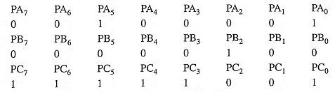
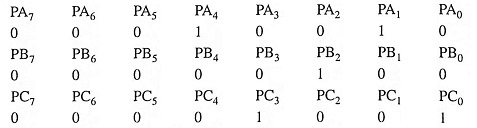
The chart shows the bit assignment of ports. Putting 0s and 1s in the required position, the data byte for each port can be derived. For example, during north to south traffic movement, the statuses of Port A, Port B and port C are as follows:
When north to south traffic movement will be ready to stop and east to west traffic must be ready for movement, the statuses of Port A, Port B and Port C are as follows:
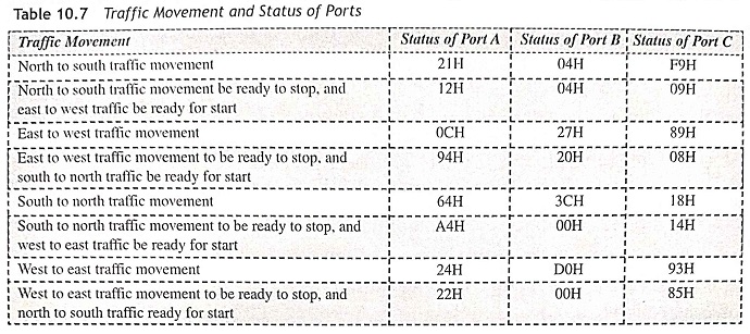
The calculated necessary data bytes of Port A, Port B and Port C for all types of traffic movement are illustrated in Table 10.7 as given below.