Time Delay Loop in Microprocessor:
Microprocessors perform different operations in sequence and one operation at a time. To complete an operation, some time is required. When some time delay is required between two operations, a Time Delay Loop in Microprocessor is used to provide it.
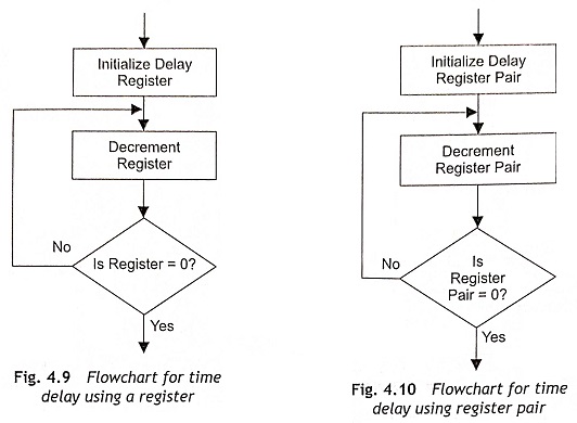
Time delay can be generated using a register or a register pair. Initially, a register is loaded with an operand or number and then the number is decremented until it reaches zero. So a conditional jump instruction is used in a delay loop to come out from the loop. The time delay depends on the number which is loaded in the register. Figure 4.9 shows the flowchart of time delay loop using one register.
Calculation of Time Delay Using One Register
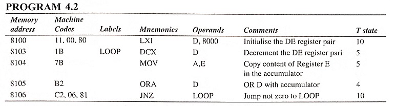
The typical instructions of a Time Delay Loop in Microprocessor are given below:
It is clear from the above instructions that MVI B, 80 requires seven clock cycles, DCR B requires 5 clock pulse and JNZ also requires 10 clock pulses during execution. When these instructions are executed, MVI B,80 instruction is executed once and the next two instructions are executed 128 times.
The number of T states for execution of LOOP is

The delay time to execute the LOOP instruction is TL = T x number of T states for execution of LOOP, where T is the system clock period. When the microprocessor operates in 5 MHz clock frequency,
![]()
The total time delay TD is calculated from the summation of time to execute instruction of outside LOOP, TOL and time to execute LOOP instruction, TL.
![]()
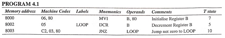
Using only one register in a delay loop, a limited time delay is generated. If very high time delay is required, a register pair will be used in place of a register. Figure 4.10 shows the flowchart for time-delay generation using a register pair. For example, a 16-bit operand is loaded in the DE register pair. Then the DE register pair is decremented by one using DCX D instruction. The DCX instruction does not set the zero flag. Therefore, additional testing will be done using some extra instructions as the JNZ instruction is executed only when the zero flag is set.
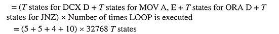
The typical instructions of a Time Delay Loop in Microprocessor using a register pair are given below:
Calculation of Time-Delay Using Register Pair
In the above instructions, LXI D, 8000 is executed once and the other instructions (DCX D, MOV A, E, ORA D and JNZ) are executed for 8000H (32768D) times.
The number of T states for execution of LOOP is
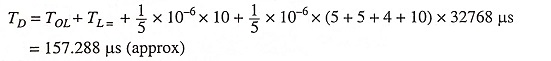
If the microprocessor clock frequency is 5 MHz, time delay in LOOP is equal to TL . TL = T x number of T states for execution of LOOP = 1/5 x 10-6 x (5 + 5 + 4 + 10) x 32768 μs = 157.268 μs (approx).
Time Delay Using Two LOOPs
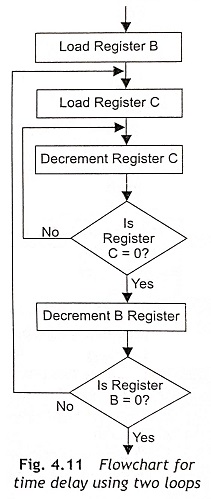
The time delay can also be generated by using two loops as depicted in Fig. 4.11. The C register is used in inner loop and the B register is used in external loop. Here, both B and C registers are loaded with numbers. Then Register C is decremented until it becomes zero. When the content of Register C is zero, decrement Register B. If the content of Register B is not zero, load the Register C with initial value and repeat the process.
The example of time delay using two loops is given below:
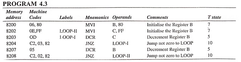
Time delay will be calculated based on time delays for LOOP-I and LOOP-II.
Time delay for LOOP-I is

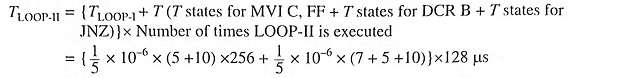
Time delay for LOOP-II is
Total delay time(TD) = Time to execute instruction of outside LOOP(TOL) + Time to execute LOOP-II
