Loop Matrix or Circuit Matrix:
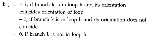
For a given directed graph, it is always possible to state which branches are involved in the formation of loops or closed circuits or meshes. For a given oriented graph, loops can be identified by marking each loop with orientation of loop current by a curved arrow. This enables to write the nodes in the loop in cyclic order. In complicated networks with many loops, it is advisable to list the nodes in selected cyclic order to avoid the confusion between oriented loop Loop currents. A loop matrix or circuit matrix is represented by Ba. For a graph with n nodes and b branches, loop matrix Ba is a rectangular matrix with b columns (equal to number of branches) and as many as rows as there are loops. The elements bhk of loop matrix has following values.
Consider an oriented graph as shown in the Fig. 5.12.
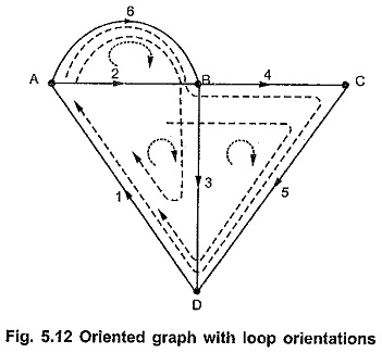
For above oriented graph various possible loops can be listed as follows.
Circuit 1 : [1, 2, 3]
Circuit 2 : [3, 4, 5]
Circuit 3 : [2, 6]
Circuit 4 : [1, 2, 4, 5]
Circuit 5 : [1, 6, 3] etc
Above listing can be expressed in tabular form as follows.
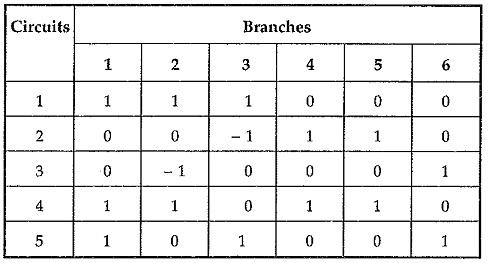
This circuit matrix Ba is given by,
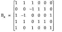
The rank of the circuit matrix Ba is given by [b – (n – 1)]. Thus for a network with many loops, the size of the circuit matrix increases. To ease simplification, a smaller subset of the circuit matrix is considered which is known as fundamental circuit (f-circuit) matrix.
Fundamental Circuit or f-circuit or Tie Set Matrix (B)
It is a subset of circuit matrix. It is represented by B.
For a given graph, select any tree and remove its all links. Then replace each link one at a time, it will form a closed path or loop or closed circuit along with some of the tree branches existing. The circuits formed by replacing each link in tree are called fundamental circuits or f-circuits or tie-sets. It is very important to select the orientation of f-circuit to coincide with that of the link completing the f -circuit.
The number of f-circuits equals the number of links. For a graph with ‘b’ branches and ‘n’ nodes, the possible f-circuits are given by [b – (n – 1)].
Consider a tree of oriented graph as shown in the Fig. 5.13 (b).
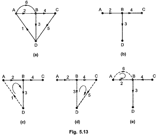
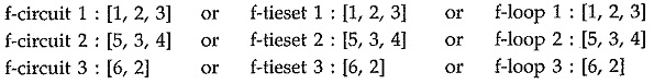
As shown above, twigs 2, 3, 4 are forming tree while 1, 5, 6 are the links which are not the part of tree. When these links are replaced, we will have three f-circuits as shown in the Fig. 5.13 (c). The orientation of each loop is coinciding the orientation of the connecting link in each f-circuit. The f-circuits or tiesets are given by writing link entry first’ and then other branches in sequence as follows,
We can write this information about f-circuits in tabular form which is known as tieset schedule. The tieset schedule for above f-circuits is as
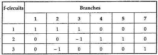
Hence f-circuit matrix B is given by,
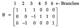
In general, matrix B is arranged such that first columns corresponding to entries of links and then columns corresponding to entries of links and then columns corresponding to entries of twigs as given below.
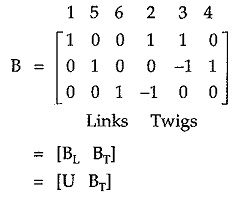
where BL is the matrix corresponding to link entries called link matrix. It is always identity matrix. BT is the twig matrix corresponding to twig entries.