Loop Analysis with Current Source or Mesh Analysis:
This method of Loop Analysis is specially useful for the circuits that have many nodes and loops. The difference between application of Kirchhoff’s laws and loop analysis is, in loop analysis instead of branch currents, the loop currents are considered for writing the equations. The another difference is, in this method, each branch of the network may carry more than one current. The total branch current must be decided by the algebraic sum of all currents through that branch. While in analysis using Kirchhoff’s laws, each branch carries only one current. The advantage of this method is that for complex networks the number of unknowns reduces which greatly simplifies calculation work.
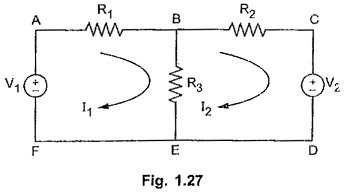
Consider following network shown in the Fig. 1.27. There are two loops. So assuming two loop currents as I1 and I2. While assume loop currents, consider the loops such that each element of the network will be included at least once in any of the loops.
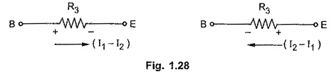
Now branch B-E carries two currents; I1 from B to E and I2 from E to B. So net current through branch B-E will (I1 – I2) and corresponding drop across R3 must be as shown below in the Fig. 1.28.
Consider loop A – B – E – F – A,
For branch B-E, polarities of voltage drops will be B +ve, E – ve for current I1 while E + ve, B – ve for current I2 flowing through R3.
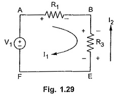
Now while writing loop equations assume main loop current as positive and Fig. 1.29 remaining loop current must be treated as negative for common branches.
Writing loop equations for the network shown in the Fig. 1.27.
For loop A – B – E – F – A,
-I1 R1 – I1 R3 + I2 R3 + V1 = 0
For loop B – C – D – E – B
-I2 R2 – V2 – I2 R3 + I1 R3 = 0
By solving above simultaneous equations any unknown branch current can be determined.
Points to be Remembered for Loop Analysis:
- While assuming loop currents make sure that at least one loop current links with every element.
- No two loops should be identical
- Choose minimum number of loop currents.
- Convert current sources if present, into their equivalent voltage sources for loop analysis, whenever possible.
- If current in a particular branch is required, then try to choose loop current in such a way that only one loop current links with that branch.
Important Note : If there exists a current source in any of the branches of the network then a loop can not be defined through the current source as drop across the current source is unknown. For example, consider the network shown in the Fig. 1.30. In this circuit, branch BE consists of a current source. So loop ABEFA can not be defined as loop from KVL point of view, as drop across the current source is not known.
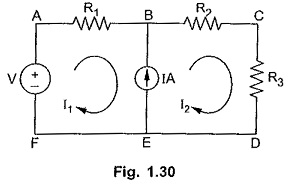
In such case, to get the required equation interms of loop currents, analyse the branch consisting of a current source independently. Express the current source interms of the assumed loop currents. For example, in the Fig. 1.30 analyse the branch BE. The current source is of IA in the direction of loop current I2. So I2 is more than I1 and we can write an equation,
I = I2 – I1
So all such branches, consisting current sources must be analysed independently. Get the equations for current sources interms of loop currents. Then apply KVL to the remaining loops which are existing without involving the branches consisting of current sources. The loop existing, around a current source which is common to two loops is called supermesh. In the Fig. 1.30, the loop ABCDEFA is supermesh.