Closed Loop Speed Control of DC Motor:
Closed Loop Speed Control of DC Motor – The converters (rectifiers and choppers) are built using semiconductor devices, which have very low thermal capacity. Consequently their transient and steady state current ratings are same. The dc motors can carry 2 to 3.5 times the rated current during transient operations of short duration’s, such as starting, braking and reversing. Higher the current, higher is the torque and faster is the transient response. Therefore, when fast response during transient operations is required, motor current is allowed to have maximum permissible value. The converter rating is then chosen equal to the maximum permissible value of motor current. Because of large current rating, the converter cost will now be higher. When fast transient response is not required, the converter current rating is chosen to be equal to the motor current rating in order to keep the converter cost low.
Open-loop drives are provided with current limit control and in order to protect the converter against current overloads. The Closed Loop Speed Control of DC Motor schemes are provided with inner current control loop in order to limit the current within a safe limit and also to accelerate and decelerate the drive at the maximum permissible current and torque during transient operations. It should, however, be noted that deceleration at the maximum current or torque will be possible when the converter used has the capability for braking operation also. It may further be noted that controlled rectifier will be used when supply is ac and chopper will be used when supply is dc.
The basic approach of closed-loop speed control below and above the speed is explained by the drive of Fig. 5.47. The drive employs inner current control loop and outer speed loop. Such a drive will operate at a constant field current and variable armature voltage below the base speed, and at a constant armature voltage and variable field current above the base speed. Both armature and field, are therefore, fed from fully-controlled rectifiers. Since, the armature is fed from a fully-controlled rectifier, forward braking is not possible; the drive will decelerate due to load torque only. Because of inner current control with current limiter, the acceleration will take place at the maximum permissible current and torque. In semiconductor converter fed drives PI (proportional and integral) controller is often used because it filters out noise which can otherwise become a problem. PI controller also gives good steady-state accuracy.
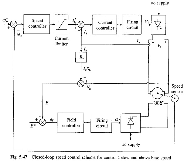
Let us first examine the operation below the base speed. In the field control loop, the back emf E is compared with a reference voltage E* which is chosen to be between 0.85 to 0.95 of the rated armature voltage. The higher value is used for motors with low armature circuit resistance. For speeds below base speed, the field controller saturates due to large value of error ef. The firing angle of field rectifier αf is maintained at zero, applying rated voltage to the field. This ensures rated field current for motor operation below base speed (ωmb). When speed reference is increased from ω*m1 to ω*m2 (ω*m2 <ωm1) due to large speed error, the current limiter saturates and sets the current reference at the maximum permissible value. The drive accelerates at the maximum available current and torque. When speed reaches close to ω*m2, the current limiter desaturates and the drive settles at speed ωm2 and at the current which gives motor torque equal to the load torque. If speed reference is reduced back to ω*m1, the current reference is set at zero and the drive decelerates due to load torque. When ωm becomes slightly less than ω*m1 motor current flows again and finally drive settles at speed ωm1 and current for which motor torque balances the load torque. For negative speed error, I*a is set at zero because negative I*a is of no use. It will however charge PI controller. When reference speed is increased again, making speed error positive, the charged PI controller takes longer time to respond, making the transience response slower.
Let us now examiner the operation above base speed. When close to base speed, the field controller comes out of saturation. Now if the reference speed is set for a speed above base speed, the current reference is set at the maximum permissible value. The firing angle of the armature rectifier αa is reduced to initially increase Va. The motor accelerates, E increases, ef decreases, reducing the field current. Thus the motor speed continues to increase and field current continues to decrease until the motor speed becomes equal to the reference speed. Since, the speed error will now be small, Va will return to a value close to original value. Thus, the speed control above base speed is obtained by field control with the armature voltage maintained near the rated value. In the field control region (above base speed), the drive responds very slowly due to large value of the field time constant.