Incidence Matrix (A):
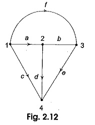
The incidence of elements to nodes in a connected graph is shown by the element node incidence matrix (A). Arrows indicated in the branches of a graph result in an oriented or a directed graph. These arrows are the indication for the current flow or voltage rise in the network. It can be easily identified from an oriented graph regarding the incidence of branches to nodes. It is possible to have an analytical description of an oriented-graph in a matrix form. The dimensions of the matrix A is n x b where n is the number of nodes and b is number of branches. For a graph having n nodes and b branches, the complete incidence matrix A is a rectangular matrix of order n x b.
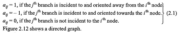
In matrix A with n rows and b columns an entry aij in the ith row and jth column has the following values.
Following the above convention its incidence matrix A is given by
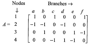
The entries n the first row indicates tha three branches a, c and fare incident to node 1 and they are oriented away from node 1 and therefore the entries a11;a13 and a16 are + 1. Other entries in the 1st row are zero as they are not connected to node 1. Likewise, we can complete the incidence matrix for the remaining nodes 2, 3 and 4.
Properties of Incidence Matrix A
Following properties are some of the simple conclusions from incidence matrix A.
- Each column representing a branch contains two non-zero entries + 1 and —1; the rest being zero. The unit entries in a column identify the nodes of the branch between which it is connected.
- The unit entries in a row identify the branches incident at a node. Their number is called the degree of the node.
- A degree of 1 for a row means that there is one branch incident at the node. This is commonly possible in a tree.
- If the degree of a node is two, then it indicates that two branches are incident at the node and these are in series.
- Columns of A with unit entries in two identical rows correspond to two branches with same end nodes and hence they are in parallel.
- Given the incidence matrix A the corresponding graph can be easily constructed since A is a complete mathematical replica of the graph.
- If one row of A is deleted the resulting (n — 1) x b matrix is called the reduced incidence matrix A1. Given A1, A is easily obtained by using the first property.
It is possible to find the exact number of trees that can be generated from a given graph if the reduced incidence matrix A1 is known and the number of possible trees is given by Det (A1AT1) where AT1 is the transpose of the matrix A1.
Incidence Matrix and KCL
Kirchhoff’s current law (KCL) of a graph can be expressed in terms of the reduced incidence matrix as A1 I = 0.
A1, I is the matrix representation of KCL, a where I represents branch current vectors I1,I2,……I6.
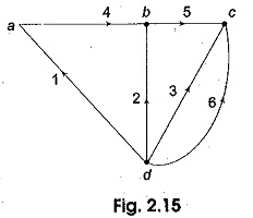
Consider the graph shown in Fig. 2.15. It has four nodes a, b, c and d.
Let node d be taken as the reference node. The positive reference direction of the branch currents, corresponds to the orientation of the graph branches. Let the branch currents be I1,I2,……I6. Applying KCL at nodes a, b and c.
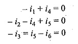
These equations can be written in the matrix form as follows
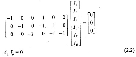
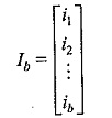
Here, Ib represents column matrix or a vector of branch currents.
A1 is the reduced incidence matrix of a graph with n nodes and b branches. And it is a (n — 1) x b matrix obtained from the complete incidence matrix of A deleting one of its rows. The node corresponding to the deleted row is called the reference node or datum node. It is to be noted that A1Ib = 0 gives a set of n — I linearly independent equations in branch currents I1,I2,……I6. Here n = 4. Hence, there are three linearly independent equations.