Types of Electromagnetic Relays:
There are two principal Types of Electromagnetic Relays:
-
Attracted armature type; and
-
Induction type.
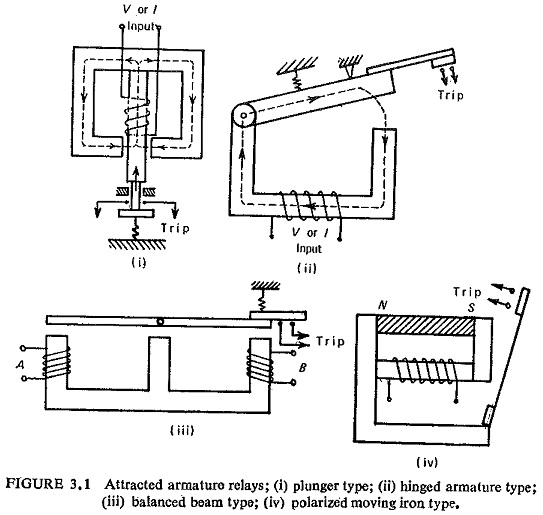
(a) Attracted Armature Type: This includes plunger, hinged armature, balanced beam and moving iron polarized relays. These are the simplest type which respond to a.c. as well as d.c. Figure (3.1) illustrates these types of relays.
All these relays have the same principle, that is, an electromagnetic force is produced by the magnetic flux which in turn is produced by the operating quantity. The electromagnetic force exerted on the moving element is proportional to the square of the flux in the air gap or the square of the current. In d.c. Types of Electromagnetic Relays this force is constant; if this force exceeds the restraining force, the relay operates reliably. In a.c. electromagnetic relays the electromagnetic force is given by
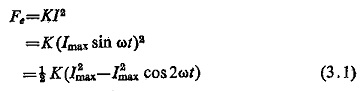
It shows that the electromagnetic force consists of two components, one constant independent of time (1/2 KI2max) and another dependent on time and pulsating at double the frequency of the applied alternating quantity (1/2 KI2max COS 2 ωt). The total electromagnetic force thus pulsates at double the frequency. The force Eq. (3.1) is plotted graphically in Fig. (3.2) which shows that Fe equals zero every half period.
If the restraining force Fr which is produced with the help of a spring is constant, the relay armature will be picked up at t1 and the armature drops off at t2. Hence the relay armature vibrates at double the frequency. This causes the relay to hum and produces noise and also is a source of damage to the relay contacts. This leads to sparking and unreliable operation of the relay operative circuit contacts due to make and break of the circuit.
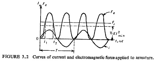
To overcome this difficulty in a.c. Types of Electromagnetic Relays the flux producing the electromagnetic force is divided into two fluxes acting simultaneously but differing in time phase, so that the resultant electromagnetic force is always positive and if this is always greater than the restraining force Fr then the armature will not vibrate. This is easily achieved by providing shading in the electromagnet as shown in Fig. (3.3).
The flux through the shaded pole lags behind the flux through the unshaded pole.
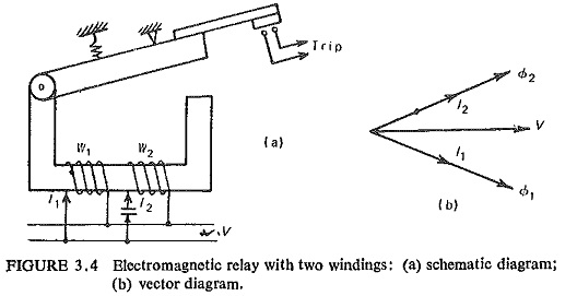
The same thing can also be achieved by providing two windings on the electromagnet having a phase shifting circuit. One simple circuit is shown in Fig. (3 4a) having two windings W1 and W2 on the same electromagnet. Figure (3. 4b) shows the vector diagram. However, the shading coil method is more simple and is used widely.
Hinged armature relays are mainly used as auxiliary relays, e.g. tripping relays, a.c. and d.c. voltage and current relays. Their volt-ampere consumption is low being of the order of 0.05 watt at pickup with one contact. The volt-ampere consumption increases with the number of contacts.
In the case of balanced beam type two quantities A and B are compared. Actually |A|2 and |B|2 rare compared because the electromagnetic forces are proportional to (ampere-turn)2. It has low ratio of reset/operating current. If set for fast operation, there is a tendency to overreach on transient conditions.
The sensitivity of the hinged armature relays can be increased for d.c. operation by the addition of a permanent magnet. This is known as a polarized moving iron relay. It is more robust in construction; most of these use leaf-spring supported armatures.
(b) Induction Relays: Torque is produced in these relays when one alternating flux reacts with the current induced in the rotor by another alternating flux displaced in time and space but having the same frequency. Induction relays are widely used for protective relaying involving a.c. quantities. High, low and adjustable speeds are possible, and various shapes of time/ operating quantity curves can be obtained. Depending on the type of rotor whether a disc or a cup the relay is known as an induction disc or an induction cup relay.
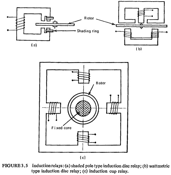
Various features of construction of an induction relay are shown in Fig. (3.5). Figures (3.5a and b) show the most common type of induction disc type relays which are also known as shaded pole type and wattmetric type of induction disc relays respectively. In the shaded pole relay the main flux is split into two fluxes displaced in time and space with the help of a shading ring, the air gap flux of the shaded poles lags behind that between the nonshaded poles. In the wattmetric type there are two magnetic systems. A phase displacement between the fluxes is obtained either by having different resistance and inductance for the two circuits or by energizing them from two different sources whose outputs are relatively displaced in phase. Many variations in the design and construction are possible to suit the required conditions. The disc may be of aluminium or copper, or it may be a hollow cylinder open at one end, i.e. cup shaped as shown in Fig. (3.5c). Normally the relay contacts are operated directly by an arm carried on the rotor spindle but in some time lag types the rotor runs at a comparatively high speed and the contacts are driven through gears.
The distance of travel of the arm carrying the bridging contact to the relay contacts can be adjusted with the help of the time multiplier setting. Taps are provided on the input side of the operating quantity which can be adjusted with the help of inserting the plug. This is known as the plug multiplier setting. A permanent magnet is provided to give eddy current breaking to the disc. This is necessary to reduce to a minimum the overrun of the disc in case the current or voltage providing the driving torque stops before the operation has been completed. A modern induction disc relay will have an overrun of not more than 2 cycles on interruption of 20 times the setting quantity.
Induction cup relays operate on the same principle as the induction motor. A rotating field is produced by the two pairs of coils shown in Fig. (3.5c). The rotating field induces currents in the cup causing it to rotate in the same direction. A control spring, and the back stop or closing of the contacts carried on an arm attached to the spindle of the cup, prevent continuous rotation. The rotation depends on the direction of rotation of the field and the magnitude of the applied voltage and/or currents and the phase angle between them. This type is very fast in operation owing to the light rotor and minimum magnetic leakages in the magnetic circuit. Relays of this type may have an operating time of less than 0.010 second. They can be made to have linear operating characteristics and a very high ratio of resetting to operating values. These are best suited where normal and abnormal conditions are very close together, so that it can be set to trip instantaneously up to 90% of the protected section as a distance relay. These are also ideal as directional relays because of their high sensitivity, speed and nonvibrating steady torque, the parasitic torques due to current or voltage alone are small.