Reflection of Electromagnetic Waves by a Conducting Surface:
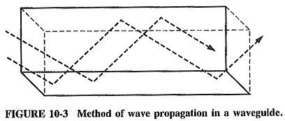
In view of the way in which signals propagate in waveguides, it is now necessary to consider what happens to Reflection of Electromagnetic Waves when they encounter a conducting surface. An electromagnetic plane wave in space is transverse-electromagnetic, or TEM. The electric field, the magnetic field and the direction of propagation are mutually perpendicular. If such a wave were sent straight down a waveguide, it would not propagate in it. This is because the electric field (no matter what its direction) would be short-circuited by the walls, since the walls are assumed to be perfect conductors, and a potential cannot exist across them. What must be found is some method of propagation which does not require an electric field to exist near a wall and simultaneously be parallel to it. This is achieved by sending the wave down the waveguide in a zigzag fashion (see Figure 10-3), bouncing it off the walls and setting up a field that is maximum at or near the center of the guide, and zero at the walls. In this case the walls have nothing to short-circuit, and they do not interfere with the wave pattern set up between them. Thus propagation is not hindered.
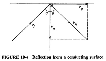
Two major consequences of the zigzag propagation are apparent. The first is that the velocity of propagation in a waveguide must be less than in free space, and the second is that waves can no longer be TEM. The second situation arises because propagation by reflection requires not only a normal component but also a component in the direction of propagation (as shown in Figure 10-4) for either the electric or the magnetic field, depending on the way in which waves are set up in the waveguide. This extra component in the direction of propagation means that waves are no longer transverse-electromagnetic, because there is now either an electric or a magnetic additional component in the direction of propagation.
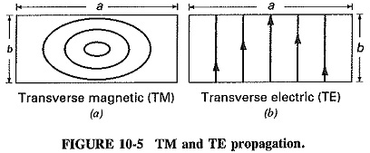
Since there are two different basic methods of propagation, names must be given to the resulting waves to distinguish them from each other. Nomenclature of these modes has always been a perplexing question. The American system labels modes according to the field component that behaves as it did in free space. Modes in which there is no component of electric field in the direction of propagation are called transverse-electric (TE, see Figure 10-5b) modes, and modes with no such component of magnetic field are called transverse-magnetic (TM, see Figure 10-5a). The British and European systems label the modes according to the component that has behavior different from that in free space, thus modes are called H instead of TE and E instead of TM.
Dominant mode of operation:
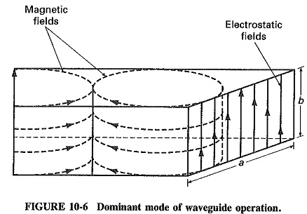
The natural mode of operation for a waveguide is called the dominant mode. This mode is the lowest possible frequency that can be propagated in a given waveguide. In Figure 10-6, half-wavelength is the lowest frequency where the waveguide will still present the properties discussed below. The mode of operation of a waveguide is further divided into two submodes. They are as follows:
- TEm,n for the transverse electric mode (electric field is perpendicular to the direction of wave propagation)
- TMm,n for the transverse magnetic mode (magnetic field is perpendicular to the direction of wave propagation)
Where
m = number of half-wavelengths across waveguide width (a on Figure 10-6)
n = number of half-wavelengths along the waveguide height (b on Figure 10-6)
Plane waves at a conducting surface:
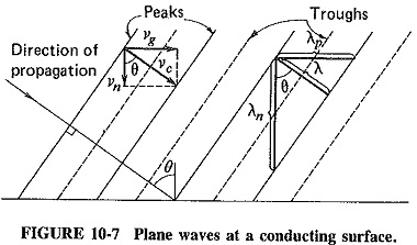
Consider Figure 10-7, which shows wave-fronts incident on a perfectly conducting plane (for simplicity, reflection is not shown). The waves travel diagonally from left to right, as indicated, and have an angle of incidence θ.
If the actual velocity of the waves is νc, then simple trigonometry shows that the velocity of the wave in a direction parallel to the Reflection of Electromagnetic Waves by a Conducting Surface, νg, and the velocity normal to the wall, νn, respectively, are given by
![]()
As should have been expected, Equations (10-1) and (10-2) show that waves travel forward more slowly in a waveguide than in free space.
Parallel and normal wavelength:
The concept of wavelength has several descriptions or definitions, all of which mean the distance between two successive identical points of the wave, such as two successive crests. It is now necessary to add the phrase in the direction of measurement, because we have so far always considered measurement in the direction of propagation (and this has been left unsaid). There is nothing to stop us from measuring wavelength in any other direction, but there has been no application for this so far. Other practical applications do exist, as in the cutting of corrugated roofing materials at an angle to meet other pieces of corrugated material.
In Figure 10-7, it is seen that the wavelength in the direction of propagation of the wave is shown as λ, being the distance between two consecutive wave crests in this direction. The distance between two consecutive crests in the direction parallel to the conducting plane, or the wavelength in that direction, is λp, and the wavelength at right angles to the surface is λn. Simple calculation again yields
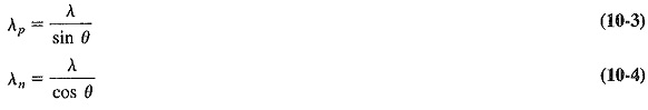
This shows not only that wavelength depends on the direction in which it is measured, but also that it is greater when measured in some direction other than the direction of propagation.
Phase velocity:
Any Reflection of Electromagnetic Waves has two velocities, the one with which it propagates and the one with which it changes phase. In free space, these are “naturally” the same and are called the velocity of light, νc, where νc is the product of the distance of two successive crests and the number of such crests per second. It is said that the product of the wavelength and frequency of a wave gives its velocity, and
![]()
For Figure 10-7 it was indicated that the velocity of propagation in a direction parallel to the Reflection of Electromagnetic Waves by a Conducting Surface is νg = νc sin θ, as given by Equation (10-1). It was also shown that the wavelength in this direction is λp = λ/sin θ, given by Equation (10-3). If the frequency is f, it follows that the velocity (called the phase velocity) with which the wave changes phase in a direction parallel to the Reflection of Electromagnetic Waves by a Conducting Surface is given by the product of the two. Thus
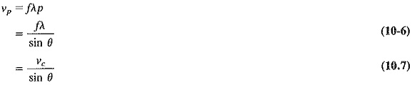
where νp = phase velocity
A most surprising result is that there is an apparent velocity, associated with an Reflection of Electromagnetic Waves at a boundary, which is greater than either its velocity of propagation in that direction, vg, or its velocity in space, νc. It should be mentioned that the theory of relativity has not been contradicted here, since neither mass, nor energy, nor signals can be sent with this velocity. It is merely the velocity with which the wave changes phase at a plane boundary, not the velocity with which it travels along the boundary. A number of other apparent velocities greater than the velocity of light can be shown to exist. For instance, consider sea waves approaching a beach at an angle, rather than straight in. The interesting phenomenon which accompanies this (it must have been noticed by most people) is that the edge of the wave appears to sweep along the beach must faster than the wave is really traveling, it is the phase velocity that provides this effect.