Series Parallel Controller with Reversing Drum:
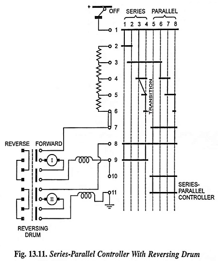
A Series Parallel Controller with Reversing Drum (with shunt transition) for two series motors is shown in Fig. 13.11.
In addition to its primary function of providing series parallel controller of dc series traction motors it also controls (i) speed and direction of motion of the vehicle (ii) magnitude of retardation during braking period and (iii) provides means to remove faulty motor if any fault occurs during the operation and operating the vehicle with the remaining motor and (iv) if possible it must also provide means to prevent its moving backward when stopped on a steep gradient.
Working Principle:
The controller is in the form of a rotating drum having insulated and interconnected segments in the form of strips, which makes contact with the fixed points (known as fingers). The controller has 8 positions, 4 positions for series and four for parallel running. The working positions of the controller (known as notches) are shown by vertical dotted lines. The segments on the rotating drum are shown by black rectangles. Fixed contacts, known as fingers, are shown by vertical row of large circular dots on the left. Across these fingers, starting resistances and reversing contacts are connected. The reversing arrangement is provided by providing an additional rotating drum known as reversing drum.
Now when the reversing drum is put in forward position and controlling drum is set in position 1, the connections with fixed points are along vertical line 1. In this position segments make contact with fixed points 1 and 2, 8 and 9. In this position current flows from + ve fixed point 1 through the drum segment, fixed point 2, all the starting resistances 2 – 6, fixed point 7, reversing drum to armature of motor No. I, series field of motor No. I, fixed points 9 and 8, armature and series field of motor No. II and returns back to the – ve terminal.
In the second position the segments of the controller drum come in contact with fixed points 1 and 3, 8 and 9 and thereby bringing some of the starting resistance out of circuit, therefore, speed of the motors increases. In the subsequent 3rd position additional step of resistance is brought out of the circuit and finally in fourth position starting resistance is reduced to zero and half of the supply voltage acts across each motor.
Further movement of the drum reinsert some of the starting resistance in the circuit and short circuit the motor No. II as the current from +ve fixed point 1 passes to fixed point 3, starting resistance, fixed points 6 and 7, reversing drum, armature and series field of motor No. 1, fixed points 9 and 10 and returns to the – ve terminal through lower two segments on the controller drum (on lines 5 to 8).
As the controller drum reaches vertical line No. 5 the motor No. II is again inserted in the circuit and operates in parallel with motor No. I. As the controller drum moves further the starting resistance is reduced and finally in vertical position 8 of controlling drum, both the motors are directly connected across the supply mains and are in full parallel.
For reversing the direction of rotation of motor, it is essential that the direction of current of either of the two (armature or field) is changed. Generally it is achieved by reversing the armature current. In the forward position of reversing drum, the current enters the armatures and series field of motors No. I and II through reversing drum from the left but when the reversing drum is placed in reverse position, the current enters the armatures of motors No. I and II from the right while the direction of field currents remains the same. Thus the direction of rotation of motors are reversed by changing the position of the reversing drum which has two fixed positions.
When the position of controller drum is changed, the arcing will take place. For suppression of the arc magnetic blow-outs are employed. The blow-out coil system consists of flat iron inserted in the movable part of the rotating drum. The reversing drum is mechanically interlocked with the controlling drum so that it may not be operated unless the controlling drum is in the ‘OFF’ position.