What is Electric Traction? – Introduction, Definition, Working, Advantages and Disadvantages
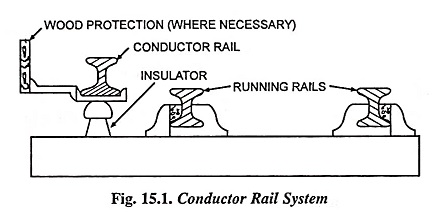
Electric traction was first introduced in Britian in the year 1890 at 600 V dc using third rail for urban and suburban services. For its application to long distance main-line service the developments were towards increasing the operating voltage and as a result the line rail system utilising 1,200 V dc was tried in Manchester-Bury line. This system of supply was not satisfactory due to inherent drawbacks, such as insufficient protection provided by the wooden planks and choking up of grooves by snow during winter season, and therefore, overhead contact system was adopted employing 1,500 V dc later on. This system is still used for suburban and main lines in many countries including our country.
In India electric traction was first introduced for suburban service in Bombay in 1925 and in Madras in 1931. It was later extended to Poona and Igatpuri. The system adopted was 1,500 V dc. The power used to be supplied to traction motors at 1,500 V dc from rotary converter substations. For 1,500 V supply two 750 V rotary converters, each of 2,500 kW capacity, were employed in series. Mercury-arc rectifiers were introduced for the first time for supplying dc power when Madras–Tambaram route was electrified. The rectifiers employed were multianode continuously evacuated steel tank type. Later on grid controlled mercury-arc rectifiers were used. Multianode air-cooled sealed type steel tank rectifiers having on-load tap changing arrangement for variation of voltage have also been employed. Nowadays solid state devices are finding increasing use in these dc substations.
After about 20 years, electric traction was introduced on the Howrah—Burdwan and Sheoraphuli-Tarakeshwar branch lines on 3,000 V dc, as at that time there was a general trend towards adopting of 3,000 V dc for electric traction.
The early applications of the three phase system were to Swiss mountain railways, and the first application to mainline railways (operating at 3,000 V) was in 1902. Subsequent development of the 3-Φ system have been entirely for mainline electrification, and the principal applications are in Northern Italy.
The single phase ac system operating at low frequency (16 2/3 Hz) found extensive applications in Switzerland, Germany, Austria and Scandinavia for suburban as well as main-line services. In America about 800 km (on the Pennsylvania and New Haven lines) are electrified on the single phase system, but at 25 Hz frequency and 1,100 V voltage. The single phase 50 Hz system has also been adopted for the electrification of the Katanga lines in the Belgian Congo.
Kando system (single phase-three phase system) was developed in Hungary in 1932.
From the reports obtained from French National Railways on relative merits and demerits of ac and dc systems it was found that ac system employing commercial frequency of 50 Hz was advantageous both financially and operationally. In 1957 Railway Board decided to adopt 25 kV, 50 Hz single phase system of electrification for all future schemes. This system gives considerable saving in the cost of overhead equipment, substations and locomotives.
The size of the overhead system is reduced because of adoption of high voltage leading to saving in the cost of supporting structures and their foundations. On account of the high voltage, the traction substations can he spaced at longer distances. AC substations are simpler than dc substations because they have only step-down transformers and necessary switchgear. However, ac traction systems have some drawbacks also like induced voltage in aerial signaling equipment and interference with neighbouring communication lines, and therefore, it will need some remedial devices to overcome such drawbacks.
In this system 25 kV, 50 Hz single phase system is employed for supplying power to the locomotives. The locomotive draws power from the overhead equipment (OHE) through sliding contact by means of pantograph. The locomotive essentially consists of (i) air circuit breaker, provided on the roof of the locomotive, mainly to disconnect the locomotive from hv supply in the event of fault in the equipment and to isolate the locomotive equipment at a voltage change point or phase change point in the overhead equipment such as before entry into the neutral section (ii) step-down transformer to step down the supply voltage to utilization level (iii) on-load tap changer for providing variable voltage (iv) converting machinery for converting ac into dc, (v) smoothing chokes for reducing the magnitude of ac component of rectified undulating dc and (vi) dc traction motors.
Advantages of Electric Traction:
- Less Maintenance
- Less Starting time
- High Starting Torque
Disadvantages of Electric Traction:
- Only electrified locations are suitable for using electric traction.
- Electric routes are dependent on electric traction.
- Communication lines close by are disturbed by power wires for electric traction.