Overhead Equipment in Electric Traction Systems:
Simplest type of overhead equipment in electric traction systems consists of a single contact wire supported either by bracket or by overhead span. The maximum distance between two consecutive supports with such a system is restricted to 30 m and speed is limited to 30 kmph. The single contact wire system, therefore, finds application for tramcars or in complicated yards and terminal stations where simplicity of layout is desired and speeds are low.
Catenary construction (either single catenary or compound catenary) is used for railways.
Automatic Weight Tension and Temperature Compensation
For sparkless current collection by pantograph collector under high speeds it is necessary that the contact wire should not only remain horizontal at the time of erection but should remain so under all conditions of temperatures and wind pressures likely to be encountered in the service. In an unregulated OHE, in which there is no provision for temperature compensation, sag and tension in catenary and contact wire are so adjusted that contact wire remains approximately horizontal at the time of erection. This type of unregulated OHE is not suitable for current collection at high speeds as encountered on main lines as tension varies inversely as temperature. It affects the stiffness of the line and its dynamic behavior.
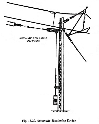
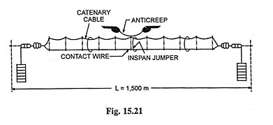
In order that the contact wire remains at the same level under all weather conditions, it is necessary to keep the tension in the catenary and contact wire constant under all temperatures likely to be encountered in service and allow movements of wires along the track which result due to changes in temperature. This is achieved by using regulated OHE at either end of the tension length (Fig. 15.20). The tensioning device consists of a pulley block or a winch with suitable reduction ratio (about 5). Increase in tension reduces the static elasticity of the OHE and makes it more uniform and thus improves the dynamic behaviour and current collection. Contact and catenary wires are given tension of about 1,000 kg each so as to limit the lateral stresses exerted on the masts and foundations due to increase in tension. Cast iron weights of 400 kg are required by the automatic tensioning device (Fig. 15.20) in order to develop tension of 1,000 kg in each of contact and catenary wire. In order to prevent longitudinal to and fro oscillations of OHE in the running condition of train, it is fixed in the centre, which is known as anticreep (Fig. 15.21). For the temperature range experienced in electrified sections in India, maximum distance between the anticreep and the end of tension length i.e., half tension length is restricted to 750 metres.
Weight tensioning has the following advantages:
- Sparkless current collection under all atmospheric conditions with consequent reduction of wear and tear of both contact wire and collecting strips of pantograph.
- Automatically taking up of creep of the conductors by the tensioning device with the passage of time.
- Some economy in the design of the supports and foundations because below 40°C temperature, the highest tensions attained are considerably less than with unregulated OHE.
- Alleviation of problem of providing adequate clearances under overline structures and in tunnels as with fixed tension in the OHE, fluctuations in its height are eliminated.
- Owing to contact tension in the conductors, there is only one critical velocity of propagation of waves in the contact wire and this velocity is usually greater than that of unregulated OHE. In high speed traction, it is very important that there should be only one critical velocity of propagation and this should be higher than the speed of the train. From this point of view, the regulated OHE is advantageous because it has only one critical velocity much higher than the maximum speed of the train.
Uninsulated Overlap
In case OHE is made continuous, which is possible by splicing of conductors, long lengths of it would be affected whenever there is a fault or damage. It will also need long time for rectification of damage. It is, therefore, essential to divide the length of elementary section into a number of sub-elementary sections each of which is separated from its adjacent one by means of what is known as an uninsulated overlap. In an uninsulated overlap, two contact wires belonging to two adjacent sub-elementary sections are run parallel to each other for at least one span and electrically connected to each other by means of jumpers. The distance between the overlaps is restricted owing to the following reasons:
- Limited size of the conductor and the weight of the drum on which conductor is rolled. This is to avoid difficulties encountered in handling in transportation.
- Necessity of isolation of portions of OHE affected by the fault for effective operation and easy maintenance. It makes necessary that overlaps are provided at lesser intervals.
- The friction of components used on swivelling type of bracket assemblies. This makes difficult to maintain uniform tension in the conductors in case the length of the OHE between anticreep and regulating equipment is long.
Length of regulated OHE is, therefore, never exceeded 1.5 km. Three span overlap is normally provided on regulated OHE with swivelling type bracket assemblies as standard overlap for 25 kV ac traction. The gap provided between two contact wires, in parallel running portion is about 20 cm which is maintained by mechanical linkage of the conductors.
Insulated Overlap
Insulated overlaps are installed chiefly for providing isolating facilities required for the operation and maintenance of OHE. In case two lengths of OHE belong to two adjacent elementary sections, there will be insulated overlap span. Insulated overlaps are also provided at feeding posts, subsectioning posts and booster stations. Insulated overlaps are similar to uninsulated overlaps except for the following:
- In order to avoid accidental contact between the contact wires, gap between them is kept more in case of insulated overlap.
- Electrical continuity between the two sections is maintained by means of jumper connections in series with isolator or interruptor. With such an arrangement, a section can be made dead and work can be carried out on the other equipment away from the overlap.
- The anchoring portion of the catenary and contact wire is separated from the rest of the portion by means of insulators provided at a distance of 2.5 m from the supports and within overlap span. The tail ends of the anchoring OHEs are connected to the other nearby overhead equipment in electric traction so as to prevent it from attaining any other potential.
In dc traction, single span insulated overlap is employed. Lateral separation between the two equipments is kept as 0.3 m for 1,500 V and 0.4 m for 3,000 V. This separation is maintained by means of insulated rods clamped on to the wires. In 25 kV ac traction system, this lateral separation is increased to 0.5 m. Three span overlap is the normal type of insulated overlap provided on 25 kV ac OHE with swivelling type of bracket assemblies.
Neutral Section
In dc traction, supply to OHE can be provided from both ends so that voltage drop can be reduced and in such a case substations operate in parallel. In case it is felt necessary, say for sake of convenience in maintenance, to have some boundary of supply between two substations, it can be had simply by means of insulated overlap. There will be no damage in this case even if pantograph bridges the OHE. But in single phase ac traction above arrangement is not permissible because adjacent substations tap different phases of the three-phase system so as to equalise load on the three phases. So momentary passing of pantograph under insulated overlap will result in short circuit between two phases of the supply system and damage the pantograph and OHE. This situation is avoided by interposing a small length of OHE, called the neutral section. It is insulated from both sides and is not connected to any source of power supply. It’s main function is to allow physically smooth and electrically sparkless passage of pantograph from one section to the other. As per Indian Railway practice, neutral section is located in the middle of two feeding posts and in front of sectioning and paralleling post.
Important precautions in connection with neutral section are given below:
- In overhead equipment in electric traction, neutral section should be located far away from stopping signals so that the train can pick up enough momentum to enable it to coast through the neutral section without difficulty because there is no power supply in the neutral section.
- Neutral section should neither be located on upgradient nor on curves because neutral section has to be negotiated with power off. The best position for its location would be at mid sections between two feeding posts, away from stopping signals and on down gradient in case of single track or straight level section in case of multi-track.
- It is essential that the length of the neutral section should be as small as possible but not of length less than the spacing between extreme pantographs. This is because the train is to negotiate the neutral section with power off and if it gets stalled in this section, there will be dislocation in the traffic and arrangements will have to be made to feed the neutral section. In case its length is shorter than the spacing between extreme pantographs, they will short circuit the OHEs supplied from different phases.
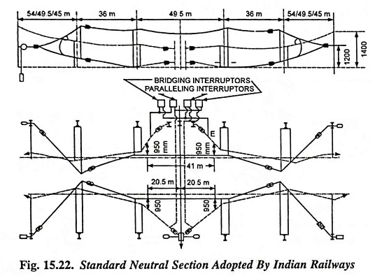
When pantographs at the extreme ends of multiple head trains are raised they are about 40 m apart. Since both the air gaps at the extreme ends of the neutral section have not to be bridged simultaneously, the minimum length of the neutral section adopted by Indian Railways is 41 metres. Standard neutral section as adopted by Indian Railways is illustrated in Fig. 15.22.
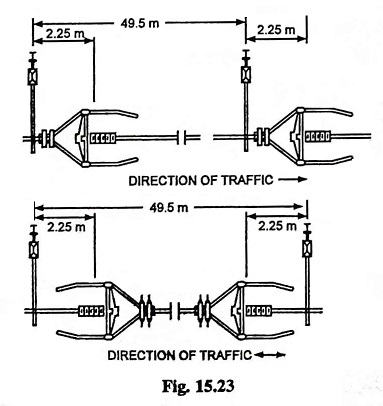
Long neutral sections are usually provided in suburban sections and steep graded sections. These neutral sections make use of section insulators in place of air gaps at the extreme ends of standard neutral section. These section insulators are fixed within the span immediately after supports in the same direction in case of double tracks and in opposite direction to each other in case of single tracks, as illustrated in Fig. 15.23.
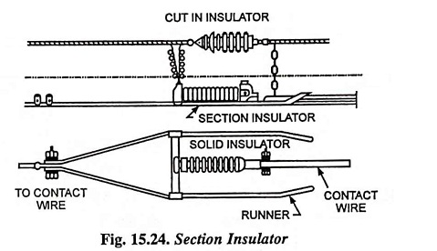
Section Insulators
Section insulators in overhead equipment in electric traction are provided for insulating OHE of one elementary section from the OHE of another adjacent elementary section such that at cross-overs from one track to the other, from main line to siding etc. as shown in Fig. 15.17. Section insulator, as illustrated in Fig. 15.24, consists of straining insulator with two runners connected to one of the contact wires. Runners are at the same height as the contact wire on the other side and so shaped as to permit smoother passage of pantograph as the train passes underneath. Runners extend and overlap the contact wire on the other side so that the locomotive draws interruption free current.