Magnetic Contactor – Definition, Working Principle and Types:
Magnetic Contactor is a electromagnetically operated switches that provide a safe and convenient means for repeatedly making and breaking branch circuits. The principal difference between a contactor and a motor starter is that contactor does not contain overload relays. Contactors are used to switch, with pilot control device, such loads as lighting, heating and controlling electric motors where overload protection is provided separately. The larger sizes are used extensively for remote control of relatively high current circuits where expense prohibits running the power leads to the remote controlling location. This is one of the main advantages of electromagnetic control over manual control. Pilot devices such as push buttons, pressure switches, float switches, limit switches or thermostats are used to provide the necessary control for operating contactors.
Working Principle:
The contactor consists of an electromagnet (having an armature, a core and a pick-up coil connected in its control circuit), main contacts (one stationary and the other movable) that make and break the power circuit, electrical interlocks that are used for blocking and control of automation and signal circuits, a blowout structure (a chute with magnetic blow-out or with special grids) that provides quick are suppression when breaking a circuit.
Contactors are manufactured for ac and dc circuits and may have one or several poles. Besides they may have normally open and (or) normally closed contacts that are switched instantaneously or with some delay. DC contactors have long pick-up coils with a small diameter and a large outside surface, which enhances cooling and enables larger currents to he carried. AC contactors are manufactured for rated voltages of 220, 380 and 500 volts and for rated currents from 20 A to 600 A. They can have from one to five main contacts and from two to four interlocks. AC contactors consist of the same elements as dc contactors. Their magnetic circuit, however, is built up from varnished electrical steel laminations to reduce eddy current losses. Three-pole ac contactors with normally open contacts are the most widespread.
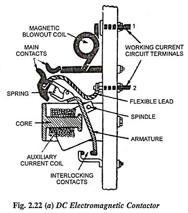
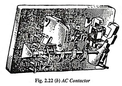
Figure 2.22 (a) shows the construction of a dc electromagnetic contactor. The auxiliary current passes through the contactor coil and attracts a steel armature to its core; the armature rotates about an axis and closes the main contacts in the working-current circuit. The spring ensures proper pressure of the movable contact. The main circuit is connected to the terminals 1 and 2; its current passes through the magnetic blowout coil, the main contacts and the flexible connecting wire. This contactor closes the contacts in the auxiliary current circuit so-called interlocking contacts which serve to perform the auxiliary control operations in addition to the main circuit. Figure 2.22(b) shows a diagram of an ac contactor.
Magnetic Starters
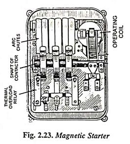
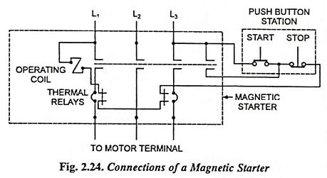
Magnetic starters are special forms of magnetic contactor designed to include thermal overload relays and electrical interlocks. Like contactors, magnetic starters are also used for remote control of electric motors. However, unlike contactors they will disconnect the motor from supply when overload arise. A magnetic starter, shown in Fig. 2.23, essentially comprises a contactor and a set of thermal relays. Each relay consists of two closely bonded strips of different alloys with different temperature coefficients of expansion. When the current flowing through such a relay exceeds its setting, it heats the bimetal element and makes it bend because the two strips increase in length by different amounts. By bending, the bimetal element opens the holding coil circuit and thus trips open the starter. The connections of a usual three-pole magnetic starter are shown in Fig. 2.24. The starter in such cases usually incorporates two built-in thermal overload relays and one electrical interlock.