Refrigeration Cycle Diagram:
For lowering the temperature of a body below that of its surroundings and then maintaining its temperature at this lower level, a continuous extraction of the heat from the body is required. The lowering or producing of low temperature in a body or a space is accomplished by a mechanism called the refrigeration cycle system. Here the heat is being generally pumped from the low level to the higher one and is rejected at that high temperature. This rejection of heat from the low level to the high level of temperature can only be performed with the help of external work according to second law of thermodynamics. The total amount of heat being rejected to the outside body consists of two parts—heat extracted from the body to be cooled and the heat equivalent to the mechanical work required for extracting it.
A refrigerator in the theoretical sense is nothing but a reverse heat engine run in the reverse direction by means of external aid. Every type of refrigeration system used for producing cold must have the following four basic units.
- Low temperature thermal sink to which the heat is rejected for cooling the space.
- Means of extracting the heat energy from the sink, raising its level of temperature before delivering it to heat receiver.
- A receiver is a storage to which the heat is transferred from the high temperature, high pressure refrigerant.
- Means of reducing the pressure and temperature of the refrigerant before it returns to the sink.
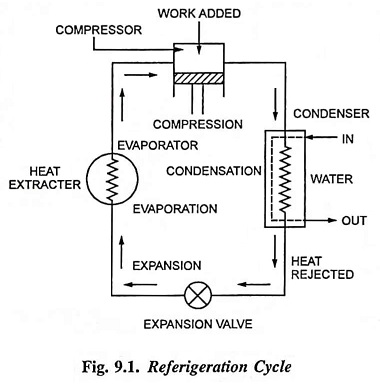
The refrigeration cycle (reversed heat engine cycle) is shown in Fig. 9.1 in which the four basic units or processes of the cycle are opposite to those of the heat engine cycle’s evaporation, expansion, condensation and compression i.e., evaporation, compression, condensation and expansion. Thus we see that by reversing a heat engine cycle completely and by changing the working agent also to the refrigerant, a refrigeration cycle is obtained.