Mixed RC Potential Divider:
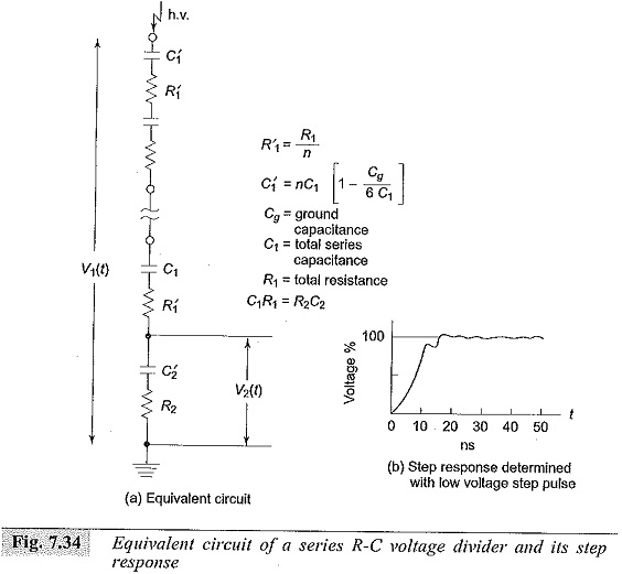
Mixed RC Potential Divider use R-C elements in series or in parallel. One method is to connect capacitance in parallel with each R′1 element. This is successfully employed for voltage dividers of rating 2 MV and above. A better construction is to make an R-C series element connection.
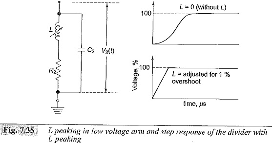
The equivalent circuit of such a construction is shown in Fig. 7.34. Such dividers are made up to 5 MV with response times less than 30 n s. The low voltage arm R2 is given “L peaking” by connecting a variable inductance L in series with R2.
 The step response of the divider and the schematic connection of low voltage arm are shown in Fig. 7.35. However, for a correctly designed voltage divider L peaking will not be necessary.
Mixed RC Potential Divider for 2 MV rating and above:
Voltage dividers used for measuring more than one million volts attenuate the criteria required to assess the dividers are:
- the shape of the voltage in the test arrangement should be transferred without any distortion to the L.V. side,
- simple determination of transfer behavior should be ensured, and
- they should be suitable for multipurpose use, i.e. for use with a.c. power frequency voltages, switching impulse voltages as well as with lightning impulse voltages.
This condition necessitates that the dividers should have broad bandwidths.
The above requirements are generally met by
- Optimally Damped RC Dividers,
- Underdamped or Low damped RC Dividers.
The high voltage arm of such dividers consists of series R-C units while the secondary arm is usually an R-C series or parallel circuit. In case of optimally damped dividers, R1 = 4√L1/Cg, where L1 is the inductance of the high voltage lead and the H.V. portion of the divider, and Cg is the equivalent capacitance to ground. Usually this resistance will be 400 to 1000 ohms. On the other hand, for low or underdamped dividers, R1 will be equal to 0.25 to 1.5 times √L/C1 where L is the inductance for the complete measuring loop and C1 is the capacitance of the H.V. part of the divider.
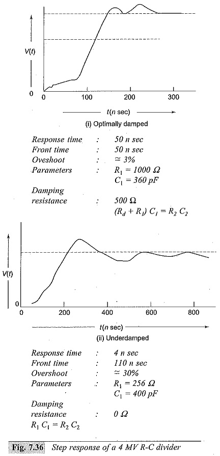
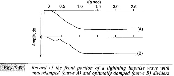
In this case the normal value of R1 lies between 50 and 300 ohms. The step response of the two types of dividers mentioned above is shown in Fig. 7.36. In actual practice, because of the large time constant (Rd + R1) C1, the optimal damped divider affects the voltage shape at the test object. Standard lightning impulses sometimes cannot be generated to the correct standard specifications. As such, Mixed RC Potential Divider are not suitable for measurements with test objects of very low capacitance. The low or underdamped R-C divider acts as a load capacitance and is suitable for applications over a broad bandwidth, i.e. a.c., switching impulses, lightning impulses, chopped waves, etc. Underdamped R-C dividers are also suitable for measurement of steep fronted impulse waves. A typical record of lightning impulse wave (1.2/50 μs wave) obtained using both the above types of dividers is shown in Fig. 7.37. It may be noted that even though the step response is poor in the case of underdamped dividers, they can be used to measure the standard impulse wave to a better accuracy.
Different Connections Employed with Potential Dividers:
Different arrangements and connections of voltage or potential dividers with a cathode ray oscilloscope are shown in Figs 7.38 and 7.39.
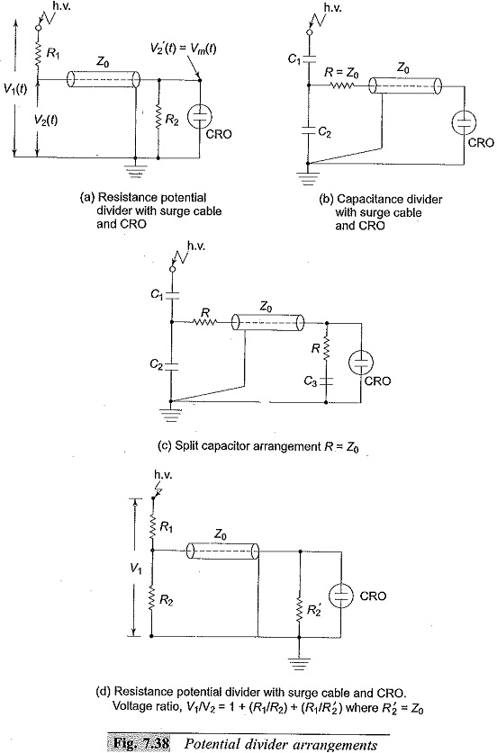
A simple arrangement of a resistance divider is shown in Fig. 7.38a. The possible errors are (i) R2 ≠ Z0 (surge impedance of the cable), (ii) capacitance of the cable and CRO shunting R2 and hence introducing distortion, (iii) attenuation or voltage drop in surge cable Z0, and (iv) ground capacitance effect. These errors are already discussed in Sec. 7.2.7. To avoid reflections at the junction of the cable and R2, R2 is varied and adjusted to give the best possible step response. When a unit step voltage is applied to the circuit shown in Fig. 7.38b, the effect of the cable is to take a fraction of the voltage [C1/(C1 + C2)] into it and cause reflections at the input end. In the beginning the cable acts like a resistance of value =Z0 the surge impedance, but later behaves like a capacitor of value equal to the total capacitance of the cable. This behaviour introduced distortion and is compensated by using a split capacitor connection as shown in Fig. 7.38c with (C1 + C2) = (C3 + Ck) [Ck = capacitance of the cable]. On the other hand if Ck/(C1 + C2 + Ck) = 0.1, the error will be less than 1.5%.
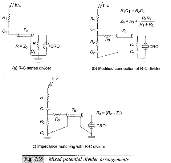
The arrangements for Mixed RC Potential Divider are shown in Fig. 7.39. The arrangement shown in Fig. 7.39a is modified and improved in the arrangement of Fig. 7.39b.
The response is greatly improved. The arrangement shown in Fig. 7.38c is simple and gives the desired impedance matching.