Magnetic Type Potential Transformer:
Magnetic Type Potential Transformer are the oldest devices for a.c, measurements. They are simple in construction and can be designed for any voltage. For very high voltages, cascading of the transformers is possible. The voltage ratio is: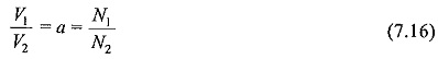
where V1 and V2 are the primary and secondary voltages, and N1 and N2 are the respective turns in the windings.
These devices suffer from the ratio and phase angle enors caused by the magnetizing and leakage impedance of the transformer windings. The errors are compensated by adjusting the turns ratio with the tappings on the high voltage side under load conditions.
Potential transformers (PT) do not permit fast rising transient or high frequency voltages along with the normal supply frequency, but harmonic voltages are usually measured with sufficient accuracy. With high voltage testing transformers, no separate potential transformer is used, but a PT winding is incorporated with the high voltage windings of the testing transformer.
With test objects like insulators, cables, etc. which are capacitive in nature, a voltage rise occurs on load with the testing transformer, and the potential transformer winding gives voltage values less than the actual voltages applied to the test object.
If the percentage impedance of the testing transformer is known, the following correction can be applied to the voltage measured by the PT winding of the Magnetic Type Potential Transformer.
![]()
where,
V20 = open circuit voltage of the PT winding,
CN = load capacitance used for testing,
C = test object capacitance (C < < CN), and
νx = % reactance drop in the transformer.