Potential Transformer Tests:
The three Potential Transformer Tests are namely,
- Polarity check,
- Ratio check and
- Phasing check.
Polarity check:
Polarity check in Potential Transformer Tests is performed in the same way as that for a CT. If the PT is of the capacitor type then the polarity of the transformer at the bottom of the capacitor stack should be checked.
Ratio check:
A simple test for ratio can be made by connecting voltmeters to the primary and secondary, one of the voltmeters sometimes being used in conjunction with a potential divider to read high primary voltages.
Another method is the comparative method. If a second PT of standard accuracy and the same ratio as the test PT is substituted for the potential divider then a fixed fraction of the primary voltage is delivered from its secondary.
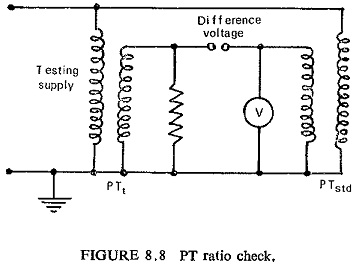
When this is applied in opposition to the secondary voltage of the test transformer, a difference voltage is obtained which is a measure of the difference in errors of the two transformers. This is shown in Fig. (8.8).
Phasing check:
The incoming secondary connections for a three-phase PT or bank of three single-phase PTs must be carefully checked for phasing. With the main circuit alive the secondary voltages between phases and neutral must be measured to verify that the phase relationship is correct. The phase rotation should then be checked with a phase rotation meter connected across the three phases as shown in Fig. (8.9).
![]()
If the three-phase PT has a broken delta tertiary winding then a check should be made of the voltage across the two connections from the broken delta VN and VL as shown in Fig. (8.9). With the rated balanced three-phase supply voltage applied to the PT primary winding; the broken delta voltage should be below 5 volts with rated burden connected.
Features of Design which Assist Maintenance:
If the following principles are adhered to, the danger of backfeeds is reduced and fault investigation is made easier.
- The drawout type of relay case construction for which the test plug can be used. A defective unit can be replaced quickly without interrupting service.
- Circuits should be kept as electrically separate as possible, and the use of common wires should be avoided except where these are essential to the correct functioning of the circuits.
- Each group of circuits which is electrically separate from other circuits should be earthed through an independent earth link.
- Where a common PT or d.c. supply is used for feeding several circuits, one of which is associated with protective gear, each circuit should be fed through separate links or fuses. When these are withdrawn the circuits should be completely isolated.
- Fuses should, where possible, be graded so that a fault on a circuit not used for protection does not interrupt supplies to the protective gear circuits.
- A single auxiliary switch should not be used for interrupting or closing more than one circuit.
- In relay panel construction some consideration should be given to the accessibility of connections as these may have to be altered when extensions are made to the gear. Modern panels are provided with special test facilities, so that no connections need be disturbed during routine testing.
- Junction boxes should be of adequate size. In case they are to be located outdoors the boxes must be made water proof.
- All wiring should be ferruled for identification.
- In relay design itself provision of high armature torque and contact pressure, jewel bearings shrouded to exclude dust, avoidance of very thin wire, use of dust tight cases, etc., reduces maintenance and increases life.