Ideal Transformer on Load:
Transfer of energy from one circuit to another circuit through mutual induction is widely utilized in power systems. This purpose is served by Ideal Transformer on Load. Most often they transform energy at one voltage (or current) into energy at some other voltage (or current).
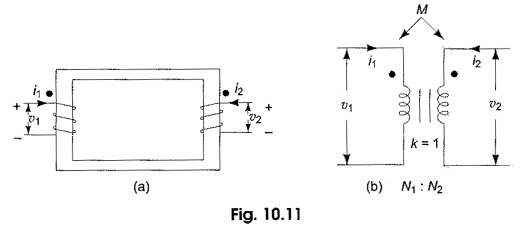
A transformer is a static piece of apparatus, having two or more windings or coils arranged on a common magnetic core. The transformer winding to which the supply source is connected is called the primary, while the winding connected to load is called the secondary. Accordingly, the voltage across the primary is called the primary voltage, and that across the secondary, the secondary voltage. Correspondingly i1 and i2 are the currents in the primary and secondary windings. One such transformer is shown in Fig. 10.11(a). In circuit diagrams, Ideal Transformer on Load are represented by Fig. 10.11(b). The vertical lines between the coils represent the iron core; the currents are assumed such that the mutual inductance is positive.
An Ideal Transformer on Load is characterised by assuming
- zero power dissipation in the primary and secondary windings, i.e. resistances in the coils are assumed to be zero,
- the self inductances of the primary and secondary are extremely large in comparison with the load impedance, and
- the coefficient of coupling is equal to unity, i.e. the coils are tightly coupled without having any leakage flux.
If the flux produced by the current flowing in a coil links all the turns, the self inductance of either the primary or secondary coil is proportional to the square of the number of turns of the coil. This can be verified from the following results.
The magnitude of the self induced emf is given by
![]()
If the flux linkages of the coil with N turns and current are known, then the self induced emf can be expressed as
![]()
![]()
But
![]()
From the above relation it follows that
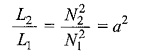
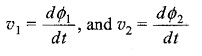
where a = N2/N1 is called the turns ratio of the transformer. The turns ratio, a, can also be expressed in terms of primary and secondary voltages. If the magnetic permeability of the core is infinitely large then the flux would be confined to the core. If Φ is the flux through a single turn coil on the core and N1, N2 are the number of turns of the primary and secondary, respectively, then the total flux through windings 1 and 2, respectively, are
![]()
Also we have
so that
![]()
Figure 10.12 shows an ideal transformer to which the secondary is connected to a load impedance ZL. The turns ratio N2/N1 = a.
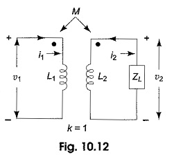
The Ideal Transformer on Load is a very useful model for circuit calculations, because with few additional elements like R, L and C, the actual behavior of the physical transformer can be accurately represented. Let us analyse this transformer with sinusoidal excitation. When the excitation are sinusoidal voltages or currents, the steady state response will also be sinusoidal. We can use phasors for representing these voltages and currents. The input impedance of the transformer can be determined by writing mesh equations for the circuit shown in Fig. 10.12.
![]()
where V1, V2 are the voltage phasors, and I1,I2 are the current phasors in the two windings. jωL1 and jωL2 are the impedances of the self inductances and jωM is the impedance of the mutual inductance, ω is the angular frequency.
from Eq.10.2
![]()
Substituting in Eq. 10.1, we have
![]()
The input impedance Zin = V1/I1
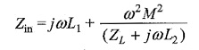
when the coefficient of coupling is assumed to be equal to unity,
![]()
We have already established that L2/L1 = a2
where a is the turns ratio N2/N1
![]()
Further simplication leads to
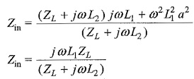
As L2 is assumed to be infinitely large compared to ZL
![]()
The above result has an interesting interpretation, that is the ideal transformers change the impedance of a load, and can be used to match circuits with different impedances in order to achieve maximum power transfer.
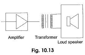
For example, the input impedance of a loudspeaker is usually very small, say 3 to 12 Q, for connecting directly to an amplifier. The transformer proper turns ratio can be placed between the output of the amplifier and the input of the loudspeaker to match the impedances as shown in Fig. 10.13.