Phasor Diagram of Transformer on No Load:
Figure 3.5 shows the schematic diagram of a Phasor Diagram of Transformer on No Load with Two Winding, i.e. the secondary terminals are open while the primary is connected to a source of constant sinusoidal voltage of frequency fHz. The simplifying assumption that the resistances of the windings are negligible, will be made.

The primary winding draws a small amount of alternating current of instantaneous value i0, called the exciting current, from the voltage source with positive direction as indicated on the diagram. The exciting current establishes flux Φ in the core (positive direction marked on diagram) all of which is assumed confined to the core i.e., there is no leakage of flux. Consequently the primary winding has flux linkages,
![]()
As per Lenz’s law, the positive direction of this emf opposes the positive current direction and is shown by + and – polarity marks on the diagram. According to Kirchhoff’s law,
![]()
and thus e1 and therefore Φ must be sinusoidal of frequency fHz, the same as that of the voltage source. Let
![]()
where
Φmax = maximum value of core flux
ω = 2πf rad/s (f = frequency of voltage source)
The emf induced in the primary winding is
![]()
From Eqs (3.3) and (3.4) it is found that the induced emf leads the flux by 90∘. This is indicated by the Phasor Diagram of Transformer on No Load in Fig. 3.6. The rms value of the induced emf is
![]()
Since E1 = V1 as per Eq. (3.2),
![]()
Even if the resistance of the primary winding is taken into account,
![]()
as the winding resistances in a transformer are of extremely small order. It is, therefore, seen from Eq. (3.6) that maximum flux in a transformer is determined by V1/f (voltage/ frequency) ratio at which it is excited.
According to Eq. (3.6) the flux is fully determined by the applied voltage, its frequency and the number of winding turns. This equation is true not only for a transformer but also for any other electromagnetic device operated with sinusoidally varying ac and where the assumption of negligible winding resistance holds.
All the core flux Φ also links the secondary coil (no leakage flux) causing in it an induced emf of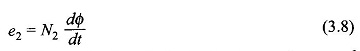 It is easy to see that e1 and e2 are in phase. This is so indicated by Phasor Diagram of Transformer on No Load in Fig. 3.6 where E1 and E2 are the corresponding phasors or in terms of the rms values. As the secondary is open-circuited, its terminal voltage is given as
![]()
From Eqs. (3.1) and (3.8) we have the induced emf ratio of the transformer windings
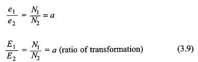
This indeed is the transformation action of the Phasor Diagram of Transformer on No Load. Its current transformation which is in inverse ratio of turns.
The value of exciting current i0 has to be such that the required mmf is established so as to create the flux demanded by the applied voltage (Eq. (3.6)). If a linear B-H relationship is assumed (devoid of hysteresis and saturation), the exciting current is only magnetizing in nature and is proportional to the sinusoidal flux and in phase with it. This is represented by the phasor im in Fig. 3.6, lagging the induced emf by 90°. However, the presence of hysteresis and the phenomenon of eddy-currents, though of a different physical nature, both demand the flow of active power into the system and as a consequence the exciting current I0 has another component Ii in phase with Ei. Thus, the exciting current lags the induced emf by an angle θ0 slightly less than 90° as shown in the phasor diagram of Fig. 3.6. Indeed it is the hysteresis which causes the current component Ii leading Im by 90° and eddy-currents add more of this component.
The effect of saturation nonlinearity is to create a family of odd-harmonic components in the exciting current, the predominant being the third harmonic; this may constitute as large as 35-40% of the exciting current. While these effects will be discussed already, it will be assumed here that the current I0 and its magnetizing component Im, and its core-loss component Ii are sinusoidal on equivalent rms basis. In other words, Im is the magnetizing current and is responsible for the production of flux, while Ii is the core-loss current responsible for the active power being drawn from the source to provide the hysteresis and eddy-current loss.
To account for the harmonics, the exciting current I0 is taken as the rms sine wave equivalent of the actual non-sinusoidal current drawn by the Phasor Diagram of Transformer on No Load. Since the excitation current in a typical transformer is only about 5% of the full-load current, the net current drawn by the transformer under loaded condition is almost sinusoidal.
From the phasor diagram of Fig. 3.6, the core-loss is given by
![]()
In a practical transformer, the magnetizing current (Im) is kept low and the core-loss is restrained to an acceptable value by use of high permeability silicon-steel in laminated form.
From the Phasor Diagram of Transformer on No Load in Fig. 3.6, the parallel circuit model of exciting current as shown in Fig. 3.7 can be easily imagined wherein conductance Gi accounts for core-loss current Ii and inductive susceptance Bm for magnetizing current Im. Both these currents are drawn at induced emf E1=V1 for resistance-less, no-leakage primary coil; even otherwise E1 ≈ V1
