Potential Difference between a and b:
Figure 3.2 shows a group of parallel charged conductors. It is assumed that the conductors are far removed from the ground and are sufficiently removed from each other, i.e. the conductor radii are much smaller than the distances between them.
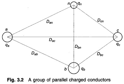
The spacing commonly used in overhead power transmission lines always meets these assumptions. Further, these assumptions imply that the charge on each conductor remains uniformly distributed around its periphery and length.
The Potential difference between any two conductors of the group can then be obtained by adding the contributions of the individual charged conductors by repeated application of Eq. (3.1).

So, the Potential Difference between a and b (voltage drop from a to b) is
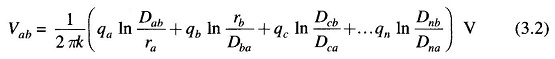
Each term in Eq. (3.2) is the potential drop from a to b caused by charge on one of the conductors of the group. Expressions on similar lines could be written for voltage drop between any two conductors of the group.
If the charges vary sinusoidally, so do the voltages (this is the case for AC transmission line),the expression of Eq. (3.2) still applies with charges/metre length and voltages regarded as phasor quantities. Equation (3.2) is thus valid for instantaneous quantities and for sinusoidal quantities as well, wherein all charges and voltages are phasors.