Coincidence Type Phase Comparator:
The basic concept of phase comparison is simpler in that it is possible to deal with signals of equal strength whose coincidence (or noncoinecidence) is readily measurable. Considering two sinusoidal signals S1 and S2, the period of coincidence of S1 and S2 will depend on the phase difference between S1 and S2. Figure (11.14) illustrates the coincidence of signals for different phase relationships in Coincidence Type Phase Comparator.
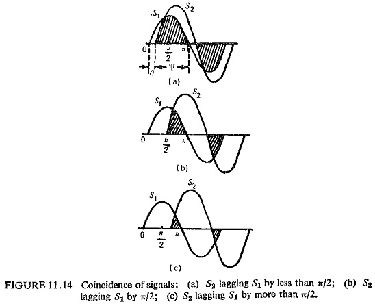
It can be seen that the period of coincidence is equal to the period of noncoincidence for a phase difference of ±90°,the period of coincidence is less than the period of noncoincidence and vice versa when the phase difference is less than ±90°.
Depending upon the phase relation of the input signals it is possible to design the circuit to give an output a Yes or a No, by measuring the period of Coincidence Type Phase Comparator.
The period of coincidence of two signals with a phase difference of θ is ψ=180-θ. Different techniques can be employed to measure the period of coincidence; the more important ones are described below.
Direct Phase Comparison:
The number of basically different methods of obtaining useful characteristics from a direct phase comparator circuit is confined to the following:
(i) Block instantaneous comparison in which the duration of polarity coincidence determines the output. The tripping criterion is that the duration of the first coincidence should exceed a specified time, usually one quarter of the power-frequency period.
(ii) Pulse comparison in which the polarity of one signal is measured during a short interval in the cycle of the second signal, usually, but not necessarily at the latter’s peak.
The block diagram of the pulse type of relay is shown in Fig. (11.15). Line voltage and current are applied to two measuring circuits, which produce complex output voltages.
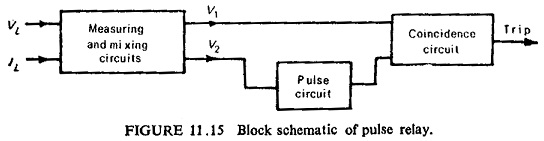
Voltage V2 is applied to a pulsing circuit which produces a positive pulse once every cycle, when V2 is at its positive maximum. V1 and the pulse derived from V2 are then applied to the terminals of a Coincidence Type Phase Comparator circuit of the type requiring both input terminals to become positive before producing any potential change at its output terminals. The criterion for relay operation is thus defined, since the coincidence circuit only yields an output when the pulse is present, and then only if V1 is positive at this instant. If θ is the angle between V1 and V2, it follows that -90°≤θ≤+90° for V1 to be positive at the instant of V2 maximum.
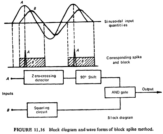
Another method for direct phase comparison is by block spike method. In this method one input is squared and the other turned into a spike preferably at the instant of its peak value; the spike and block signals are then fed through an AND gate. Coincidence Type Phase Comparator of input signals occurs only for -90°≤θ≤+90°. Figure (11.16) illustrates the schematic block diagram and wave forms.
Phase Splitting Technique:
In this method two phase shifted components (±45°) are obtained for each of the input signals and, these four components are fed to an AND gate. An output results if all the four are simultaneously positive at any time in the cycle. Referring to Fig. (11 .17) it can be seen that output will be obtained for -90°≤θ≤+90°. The block schematic is also shown in Fig (11.17).
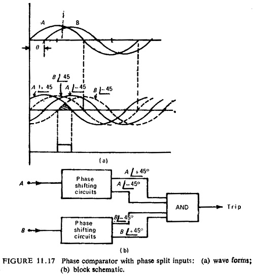
Because of the time constants of the phase shifting circuits the method is slightly slower than the previous method. By using two such comparators one for each polarity the time of operation can be reduced to less than half a cycle.
Integrating Phase Comparison:
In this method the time overlap of the two sinusoidal inputs is measured for each cycle by integrating the output of an AND gate through which they are fed. The period of coincidence is measured, and only if it exceeds 90° (for a symmetrical comparator) the output is obtained, so that the condition is -90°≤θ≤+90°.
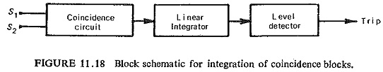
In earlier integrating phase comparators transistor-type AND gate was employed. In recent types the periods of coincidence are integrated and then fed into a level detector, the critical operating threshold of which occurs when the periods of coincidence and noncoincidence are equal, i.e. θ=±90°.. Figure (11.18) shows the basic arrangement for the integration of coincidence blocks.
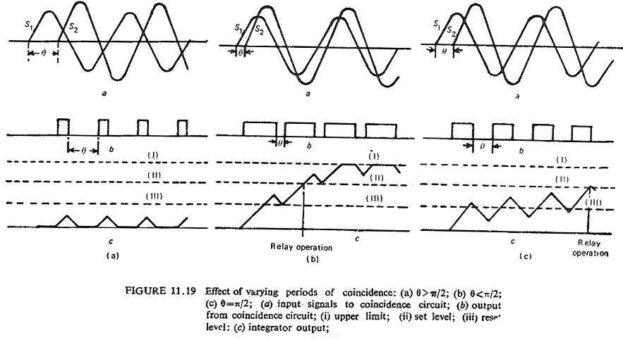
The input quantities S1 and S2 are compared in a coincidence circuit producing standard output pulses, which are positive when S1 and S2 are of the same polarity and negative when they are of opposite polarity. The pulses are applied to an integrating circuit whose output increases linearly during the time when the pulse is positive and falls at the same rate when the polarity reverses. The level detector switches when the integrator output exceeds some preset value, and resets when the output falls below some second value. The operation resulting from differing coincidence periods is illustrated in Fig. (11.19). The rise and fall rates in the integrator are at the designer’s disposal, so that the critical phase angle may be set to any desired value. Both the level detector set and reset levels are critical in relation to the total excursion limits of integrator linearity and also to the slope of the output.
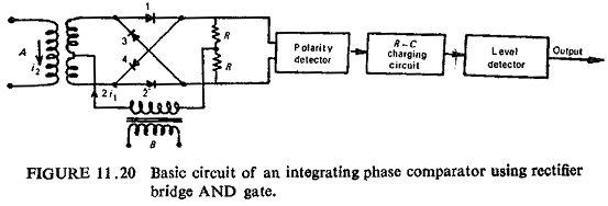
Another integrating phase comparator uses rectifier bridge AND gate. This has advantage in its simplicity and economy. This uses a rectifier bridge with a consequent polarity, detection circuit. The basis circuit is shown in Fig. (11.20) which uses inputs in the current form.
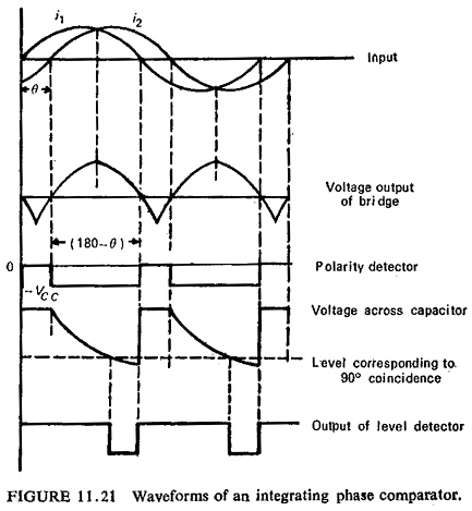
The output current of the rectifier bridge supplied to a centre tapped resistance R-R is at any moment equal to the smaller of the two input currents. The path of the current through the bridge is established by the larger of the two currents and depends upon their relative instantaneous polarity. If i1>i2 the current will flow in rectifiers 1 and 2 if i1 is positive, and in rectifiers 3 and 4 if i1 is negative. If i2 > i1 the current flows in rectifiers 1 and 4 if i2 is positive and rectifiers 2 and 3 if i2 is negative. If i1 and i2 have the same polarity the voltage across R-.R (output voltage) is positives whereas this is negative if the two currents have opposite polarities (see Fig. (11.21)). In other words the output voltage is positive during positive and negative coincidence periods; and negative during the period of anti-coincidence (opposite polarities). The time of operation with single bridge is less than half a cycle.