Comparator Equation in Power System Protection:
Comparator Equation in Power System Protection – Taking a very general case to cover the complete range of conventional relay characteristics, let S1 and S2 be the two input signals such that when the phase relationship or magnitude relationship obeys predetermined threshold conditions, tripping is initiated. The input signals are derived from the primary power system via current and voltage transformers. These signals may be derived from the primary voltage or current or from both, the latter necessitating some form of mixing device such as a current voltage transactor as shown in Fig. (4.1).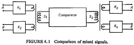
Let
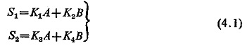
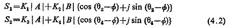
where K1 and K3 are scalar constants and K2 and K4 vector constants with angles θ2 and θ4, respectively. Taking A as the reference vector and vector B to lag A by an angle Φ, Eq. (4.1) reduces to
Analysis for Amplitude Comparator:
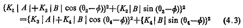
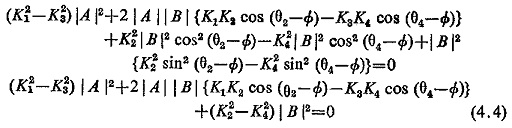
If the criteria for operation is given by |S1|≥|S2|, then at the threshold of operation |S1|=|S2|, equating the moduli of expression (4.2)
Rearranging the terms
Dividing by (K22-K24) |A|2
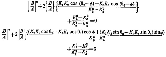
or
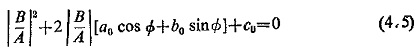
where
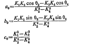
Equation (4.5) represents the equation of a circle on the β-plane having |B/A| cos Φ and j |B/A| sin Φ as coordinates represented as |B/A|p j |B/A|q. This circle has
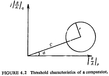
Radius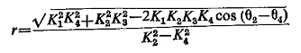
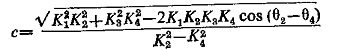
and
Similarly Eq. (4.4) can be plotted in the α-plane by dividing it by (K21 – K23) |B|2.
Analysis for Phase Comparator:
The two quantities to be compared are S1 and S2. If α is the phase angle of input S1 and β that of S2, the relay operates when the product of S1 and S2 is positive. The product is maximum when the two quantities are in phase. All the conventional characteristics of relays can be obtained with a symmetrical phase comparator with (α – β) = ±90°. Therefore, this is the threshold condition, i.e.
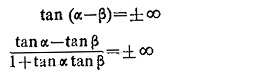
that is, when
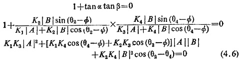
This equation is again similar to Eq. (4.4) and can be plotted on the β-plane. Dividing Eq. (4.6) throughout by K2K4|A|2cos(θ2-θ4) we get
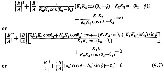
where
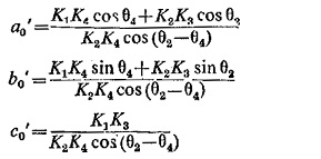
The circle has
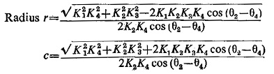
Values of r and c for plot on the α-plane can be obtained, similarly.
In most relays at least one of the constants K(i.e. K1, K2, K3, K4) is zero and two of them are often equal. Also the angle of the two vector constants is usually the same. This makes the practical case relatively simple.
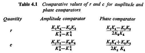
If θ2 = θ4 the values of r and c in the two cases are tabulated in Table 4.1.
Duality Between Amplitude and Phase Comparators:
Equations (4.4) and (4.6) represent the general operating characteristics of the relays using the amplitude and phase comparators respectively. These are Comparator Equation in Power System Protection of a circle on complex planes and indicate that an operating characteristic equation can be obtained either by a phase comparator or by an amplitude comparator through proper selection of the four constants K1 through K4. This further suggests the possibility of a simple relation between the two comparators and it can be proved that an inherent amplitude comparator becomes a phase comparator and vice versa, if the input quantities are changed to the sum and difference of the original two input quantities.
Consider the operation of an amplitude comparator with input signals A and B. It operates, say, when
![]()
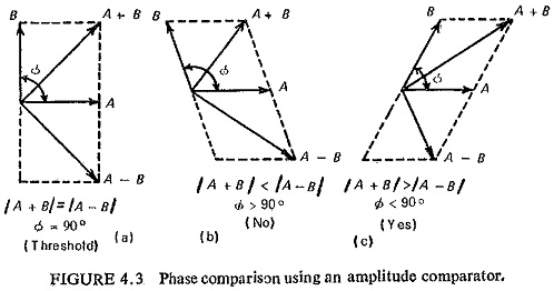
If the inputs are changed to (A + B) and (A — B) so that it operates when
![]()
It has now become an inherent phase comparator as shown in Fig. (4.3) vector diagram, i.e. if the inputs are changed to (A + B) and (A—B) the original amplitude comparator would compare phases of A and B.
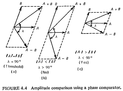
Similarly, a phase comparator working with inputs A and B, operates when A and B have same directional sense. If now the inputs are changed to (A + B) and (A—B) it would operate when (A + B) and (A—B) have the same directional sense, i.e. |A| > |B| as shown in Fig. (4.4). Such comparators are known as converted comparators.
Though a given relay characteristic can be obtained using either of the two comparators, consideration of the constants calculated for required characteristics would indicate which type of comparator is preferable. In general an inherent comparator is better than the converted type, because if one quantity is very large compared with the other, a small error in the large quantity may cause an incorrect comparison when their sum and difference are supplied as inputs to the relay.
Electromagnetic Comparators:
Electromagnetic relays that work inherently as amplitude comparators are: hinged armature structure, plunger structure, balanced beam structure, induction disc structure with shaded pole driving magnets; those working inherently as phase comparators are: induction cup structure, induction disc structure with wattmetric type driving magnets, induction dynamometer structure.