Torque Equation of Synchronous Motor:
Figure 5.36 shows a Torque Equation of Synchronous Motor with a round rotor. The rotor is initially stationary with fixed north-south poles created by dc excitation. Let the 3-phase winding of the stator be connected to a 3-phase supply of fixed voltage V (line) and fixed frequency f (this is known as the infinite bus). As a result, 3-phase currents flow in the stator winding creating a rotating magnetic field rotating at synchronous speed ns ( = 120 f/P) in the counter-clockwise direction (say). Since the rotor is stationary and cannot pick up speed instantaneously (inertia effect), the two fields move relative to each other resulting in zero average torque. As such the motor is non-self-starting.

Consider now that the rotor is run by auxiliary means to a speed close to synchronous in the direction of rotation of the stator field. The two fields now have the opportunity of locking into each other or, in other words, the rotor pulls into step with the stator field and then on runs at exactly synchronous speed. It is easily seen from Fig. 5.36 that the electromagnetic torque developed (T) acts on the rotor in the direction of rotation of rotor and balances the load torque TL. The mechanical power therefore flows to the load (motoring action) and, by the principle of conservation of energy, an equal amount of electrical power (plus losses in the device) are drawn from the electric supply. It is also seen from Fig. 5.36 that for a given TL, the rotor field lags behind the stator field by an angle α or behind the resultant field by an angle δ. The Torque Equation of Synchronous Motor is given by the expression of Eq. (5.58), i.e.
It may be seen that the negative sign has been deleted from the torque expression with the understanding that the torque acts in a direction to align the fields (it is indicated by an arrow sign in Fig. 5.36).
If the stator winding resistance and leakage reactance are assumed negligible (a fair assumption), the induced emf of the stator winding balances the terminal voltage, i.e.
![]()
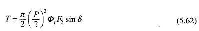
For a fixed terminal voltage, therefore, the resultant flux/pole is almost constant, independent of the shaft load. F2, the peak of rotor mmf wave being dependent upon the rotor current (dc), is constant for fixed excitation. Equation (5.62) under conditions of constant terminal voltage and constant rotor excitation can therefore be written as
![]()
where δ is positive when the rotor field lags behind the resultant field and would be negative otherwise. The angle δ is known as the torque angle or power angle.
The plot of electromagnetic torque developed by the synchronous machine is shown in Fig. 5.37. The machine operates at fixed δ for a given mechanical load torque (say (δ1 for TL1) and runs at synchronous speed. As the load torque is increased to TL2 > TL1, the rotor decelerates and the angle δ increases to a new steady value δ2 > δ1 as shown in Fig. 5.37. Of course, the machine settles at the new operating angle in an oscillatory manner and its steady speed is once again synchronous. The field coupling of the stator-rotor acts like a spring coupling and combined with rotor inertia, the system is oscillatory in nature. However, these oscillations die out after every disturbance because of the damping contributed by the mechanical and electrical dissipative effects that are present in the machine.

It is also observed from Fig. 5.37 that the maximum torque developed by the motoring machine is at δ= 90° and is called the pull-out torque (or pull-out power); power being proportional to torque as the machine speed is synchronous, independent of load. If the motor is loaded with torque (power) more than Tpull-out, the developed torque reduces (Fig. 5.37) and the rotor lag angle increases monotonically till the rotor-stator field-bond snaps, i.e. the rotor falls out of step. The machine will finally come to a stop and must, as a precautionary measure, be disconnected from the supply much before that. It is easily seen from the expression of Eq. (5.62) that the pull-out torque can be increased by increasing the stator terminal voltage and/or rotor field excitation.
With negative δ, i.e. rotor field leading the resultant field in the direction of rotation of the rotor, the electromagnetic torque as seen from Fig. 5.38 is now developed in a direction opposite to that of the rotor rotation and must be balanced by an external mechanical torque TPM (provided by a prime-mover) for the rotor to run at synchronous speed maintaining the locking of the rotor and stator fields. The mechanical power now flows into the rotor and the electrical power flows out of the stator to the infinite bus. The rotor readjusts its angle of lead such that the electrical output equals the mechanical input minus losses. If the mechanical input is more than the maximum electrical power developed (corresponding to generator pull-out torque, δ=90°), the rotor accelerates and falls out of step, i.e. the synchronism between the rotor and stator fields is lost.

To summarize, Torque Equation of Synchronous Motor has a synchronous locking between the stator and rotor fields with the rotor field lagging the resultant air-gap field in motoring operation and leading the resultant field in generating operation. The electromagnetic torque developed is a sine function of angle δ, between the rotor field and the resultant field; as a result the machine falls out of step and loses synchronism if conditions are created for δ to increase beyond ±90°. Within this range the machine operates at synchronous speed under varying load conditions. Further, the machine is non-self starting as a motor.