Separately Excited DC Motor for Dynamic Analysis:
Separately Excited DC Motor for Dynamic Analysis – The DC machines are quite versatile and are capable of giving a variety of V-A and speed-torque characteristics by suitable combinations of various field windings. With solid-state controls their speeds and outputs can be controlled easily over a wide range for both dynamic and steady-state operation. By addition of the feedback circuit, the machine characteristics can be further modified. The aim of this section is to study dc machines with reference to their dynamic characteristics.
For illustration, let us consider the separately excited dc machine shown schematically in Fig. 7.68. For ease of analysis, the following assumptions are made:
- The axis of armature mmf is fixed in space, along the q-axis.
- The demagnetizing effect of armature reaction is neglected.
- Magnetic circuit is assumed linear (no hysteresis and saturation). As a result all inductances (which came into play in dynamic analysis) are regarded as constant.
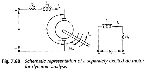
The two inductance parameters appearing in Fig. 7.68 are defined below:
- La = armature self-inductance caused by armature flux; this is quite small and may be neglected without causing serious error in dynamic analysis
- Lf = self-inductance of field winding; it is quite large for shunt field and must be accounted for
Mutual inductance (between field and armature) = 0; because the two are in space quadrature.
Further for Separately Excited DC Motor for Dynamic Analysis it is convenient to use speed in rad/s rather than rpm.
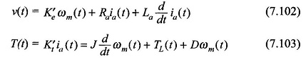
Applying Kirchhoff’s law to the armature circuit,
![]()
where
![]()
Similarly for the field circuit,
![]()
For motoring operation, the Separately Excited DC Motor for Dynamic Analysis for the mechanical system is
![]()
where
J = moment of inertia of motor and load in Nms2
D = viscous damping coefficient representing rotational torque loss, Nm rad/s
Energy storage is associated with the magnetic fields produced by if and ia and with the kinetic energy of the rotating parts. The above equations are a set of nonlinear (because of products if(t)ωm and if(t)ia(t) state equations with state variables if, ia and ωm. The solution has to be obtained numerically.
Transfer Functions and Block Diagram of Separately Excited DC Motor:
In the simple linear case of motor response to changes in armature voltage, it is assumed that the field voltage is constant and steady-state is existing on the field circuit, i.e. If = constant. Equations (7.98), (7.100) and (7.101) now become linear as given below
Laplace transforming Eqs (7.102) and (7.103),
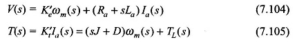
These equations can be reorganized as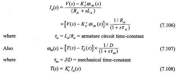
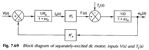
From Eqs (7.106)—(7.108), the block diagram of the motor can be drawn as in Fig. 7.69. It is a second-order feedback system with an oscillatory response in general. It is reduced to simple first-order system, if La and therefore τa is neglected.
Shunt Generator Voltage Build-up:
The qualitative explanation for the voltage build-up process in a shunt generator has already been discussed. Here the mathematical treatment of this problem will be given, which in fact boils down to the solution of a nonlinear differential equation.
Referring to Fig. 7.70 it is seen that for any field current the intercept ab, between the OCC and the Rf-line gives the voltage drop caused by the rate of change of Φf and the intercept bc gives the drop in the field resistance. The two together balance out the generated emf ea (neglecting ifRa, the armature drop). Thus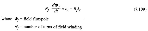
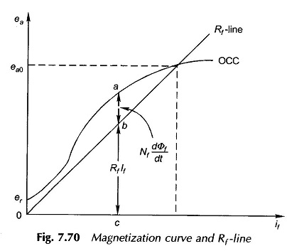
The field flux Φf is greater than the direct axis air-gap flux Φd because of leakage.
Taking this into account
![]()
Here σ is known as the coefficient of dispersion.
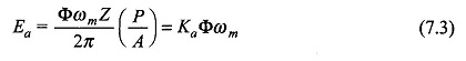
Recalling Eq. (7.3),
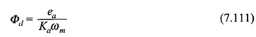
Substituting Eqs (7.110) and (7.111) in Eq. (7.109),
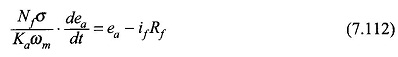
Multiplying numerator and denominator by NfPag
where
Pag is the permeance of the air-gap/pole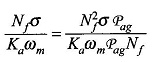
It is easily recognized that the numerator is the unsaturated value of field inductance, Lf, and the denominator is the slope of the air-gap line. Both are constants. Hence,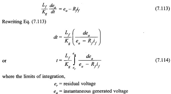
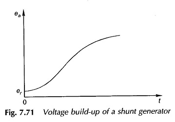
This integral can be evaluated graphically by summing up the areas on a plot of 1/(ea – Rf if) against ea. This approach is employed to plot ea against time. The theoretical time needed for the generated emf to attain the no-load value, ea0 would be infinite; hence in practice the time needed to reach 0.95 ea0 is taken as the time needed to reach ea0. The variation of ea with time is plotted in Fig. 7.71.
The response is rather sluggish since only small voltage differences (= ea – Rfif) contribute to the flux build-up (Φf).