Load Commutated Chopper Circuit:
In this method of Load Commutated Chopper Circuit, the load current flowing through the thyristor is made to become zero while the motor current is conducted by the free-wheeling diode. Figure 10.36(a) shows the circuit of a Load Commutated Chopper. The thyristor pairs Th1Th2 and Th3Th4 alternatively conduct the load current. The current conducted by any pair reduces to zero by the charging of capacitor C.
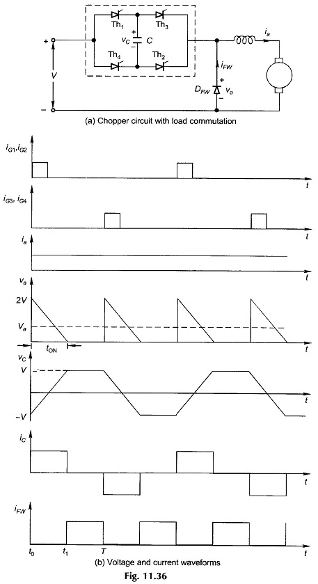
Voltage and current waveforms for the Load Commutated Chopper are shown in Fig. 11.36(b). It is assumed that in the cyclic operation, C is charged negatively when at t = t0, the thyristors Th1Th2 are fired. The voltage at motor terminals immediately jumps to 2 V. The motor circuit, because of being inductive, draws almost constant current. Capacitor C therefore gets charged positively at a uniform rate and the voltage at motor terminals falls linearly. The capacitor is fully charged positively at t = t1, the current through the conducting thyristors (Th1Th2) becomes zero and these go into the blocking mode. The motor current from this instant onwards is conducted by the free-wheeling diode DFW. At the end of one period (t = T), thyristors Th3Th4 are fired. This places the fully charged capacitor across Th1 Th2, reverse-biasing them and turning them off. The cycle now repeats.
The average value of the chopper output voltage is controlled by changing the firing frequency of the choppers. It is thus a frequency-modulated chopper. For a constant load current,
The output voltage is
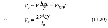
where
- f= chopper frequency.
At maximum chopper frequency,

Hence
![]()
Then from Eq.(11.20)
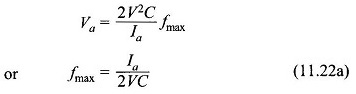
The value of the capacitor is chosen for maximum load current Ia max . From Eq.(11.22a) this value is