DC Chopper:
DC Chopper are mainly dc to dc single stage conversion devices which provide a variable voltage on the load side when fed from a constant dc voltage source. The commutation of the current from the thyristors cannot be achieved by means of supply voltage. The necessary reactive power for the converter must be provided by means of energy storage elements in the circuit itself. A continuously variable voltage is available at the output terminals for feeding dc motors. This is more effective method than resistance control because of the absence of losses. The choppers can be used for two and four quadrant operation of dc motors.
DC Chopper Working Principle
The basic circuit of a dc chopper is shown in Fig. 3.75. The main thyristor T1 is turned ON and OFF periodically, so that the supply voltage Vd is available at the output as a pulse train. By changing the ON period of the thyristor the average voltage of the load can be varied. The switching of the thyristor is accomplished by means of a firing pulse from a control circuit. The turn off of the thyristor at the desired instant is achieved by a series circuit of an auxiliary thyristor and a capacitor connected across the main thyristor.
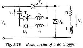
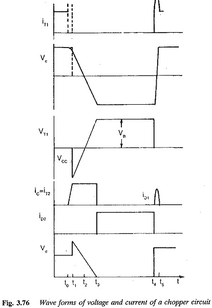
A firing pulse is provided by the same control circuit to the auxiliary thyristor. This goes into conduction, applying the capacitor voltage to the main thyristor in the reverse direction. The value of the capacitor is so chosen that the main thyristor has a negative voltage, and remains current free for a time greater than the turn off time (tq) of the thyristor, so that the thyristor T1 regains its positive blocking capability and a satisfactory commutation of the load current to the auxiliary thyristor takes place. The capacitor gets charged further by means of this constant load current, as shown in Fig. 3.76(b).
When it gets charged to Vd in the opposite direction the auxiliary thyristor ceases conduction. The current has now been transferred to the free wheeling diode (D2) which is there in the circuit to provide an alternative path for the load current when the main thyristor is switched off. This is required when the load is inductive. The free wheeling diode conducts until the main thyristor is again fired after the completion of Toff. Another circuit, comprising a diode and an inductance is placed in parallel to the auxiliary thyristor. This forms a resonating circuit with the commutating capacitor of the polarity needed for commutation of the main thyristor. When T1 is fired in its sequence a local circuit is formed by the commutating capacitor, main thyristor T1 the inductance L2 and D1.
The capacitor discharges through the circuit. After half the cycle of oscillation of the circuit the capac-itor is charged to Vd (in ideal conditions) to a polarity required for the next commutation. The diode blocks further discharge of the capacitor, thereby trapping the charge on the capacitor for the next commutation. The volt-age and current waveforms are depicted in Fig. 3.76, To avoid the high rates of change of current in the thyristors, additional inductances are provided. Sometimes the line inductances may suffice in protecting the main thyristor from di/dt.
During the commutation the time taken by the commutating capacitor to reach zero voltage after the auxiliary thyristor is fired, is![]()
This is the circuit turn off time and the negative voltage appears across the main thyristor for ts. For satisfactory commutation the thyristor must acquire its positive blocking capability. In other words
![]()
Using this equation, the minimum value of capacitance can be determined using the formula
![]()
Thus the minimum Value of the capacitance for commutation is directly proportional to the load current and the turn off time of the thyristor. The capacitance depends directly upon the source voltage. To limit the size of the capacitor, fast thyristors with a small turn off time (tq) are used. There is a chance of failure of commutation if the capacitor is charged to a voltage lower than Vd, for which it has already been designed. Fluctuations in Vd may also cause difficulties in thyristor commutation. The load current should not be below the value of ld for which the capacitance is designed.