Chopper Circuit with Input Inductance:
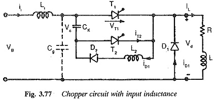
The preceding discussion of the chopper assumes ideal conditions and does not consider the effects of inductances in series with the thyristors. With choppers of large power, the leads connecting the Chopper Circuit to the supply have a definite amount of inductance (Le). Also, reactors are placed in series with the thyristors, to protect them from di/dt. These inductances affect the performance of the Chopper Circuit with Input Inductance and sometimes cause a failure of commutation. The energy stored in these inductances is transferred to the capacitor, thus increasing its voltage.
The input inductance has the disadvantage of increasing the voltage across the commutating capacitance. If the inductance is very large this voltage may attain very high undesirable values. Therefore a smoothing capacitor is required at the input. The capacitor and input inductance must resonate at a frequency that is 1/3rd the chopper frequency. When a Chopper Circuit with Input Inductance is used for traction purposes, the input inductance varies and its minimum value must be considered. This frequency requirement is satisfied by an extra inductance between the line and the chopper. The value of this inductance is chosen such that the circuit formed by the capacitor, this and line inductance resonates at a frequency less than 1/3 chopper frequency.
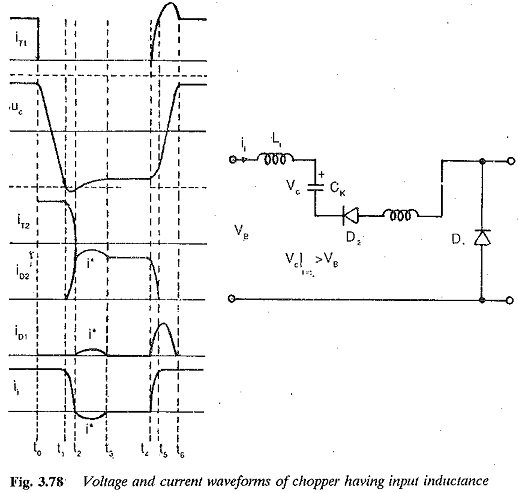
The increased charge makes the corresponding energy flow to the source via the free wheeling diode D2 and D1. The inductance LK and commuting capacitance form a resonant circuit, and a sinusoidal current is introduced which makes the voltage across the capacitor less than Vd (Fig. 3.77). When the thyristor T1 is fired after the successful free wheeling of D2, the voltage to which the capacitor gets recharged is less than Vd. Consequently the circuit turn off time ts decreases. The effect is pronounced at large load currents. If ts becomes less than tq, the commutation failure occurs. The voltage and current waveforms as affected by the inductances are shown in Fig. 3.78.
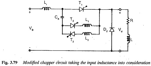
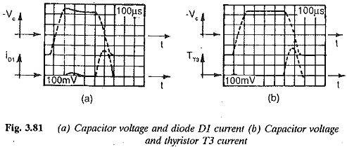
Commutation failure may be avoided by replacing the diode D1 with a thyristor T3. This introduces no additional complications in the control, since it is fired along with T1. The commutating capability is clearly improved because the capacitor voltage is larger at larger currents. The introduction of T3 (Fig. 3.79) and its firing along with T1 prevents the flow of extra current, which is responsible for the reduction of capacitor voltage. The voltage of the capacitor is maintained at Vd.
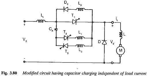
The duration of the charging process of the condenser is dependent on the load current. Because of this, a minimum TON has to be assured and the time ratio TON/T (a) cannot be varied up to zero. There is a lower limit for a (i.e. TON/T), which increases as the load current decreases. At very light load currents the capacitor may not be charged to sufficient voltage and commutation failure may occur. Therefore sufficient TON must be provided for the capacitor to charge to Vd. As Id approaches zero the charging and discharging of the capacitor takes very long time control of the Chopper Circuit with Input Inductance will not be of high quality. This difficulty can be avoided by making the commutation and associated processes independent of load current.
To achieve this an additional circuit containing a series combination of a diode D4 and inductance L4 is connected in parallel to the main thyristor, as shown in Fig. 3.80. The charging of the capacitor is independent of load current. When the auxiliary thyristor is fired, the current gets transferred to T2. The load current flows through the capacitor and discharges it. The capacitor forms a resonant circuit with L3+L4 and is quickly charged to a higher voltage. T2, therefore, conducts both the load current and this charging current. The charging current flows via D4 and L4, and the charging becomes independent of load current. These conditions are shown in Fig. 3.81. By a proper choice of inductance in the resonating circuit, the resonant frequency can be varied. The minimum value of TON is decided by the resonant frequency. It must be half the period of this frequency. The lower limit of TON can be made as small as possible by selecting the inductance properly.
