AC Input:
The, ac input modules that are commonly available work with 24, 48, 110 and 220 V. It is important to use the one that fits the needs based upon the inputs devices (voltage) used.
These day, ac input modules are less common than dc input modules. This is because most of the sensors used today have transistor outputs. A transistor does not operate with ac voltages. Most commonly, the ac voltage is being switched through a limit switch or other switch type. If a sensor is used it probably is operating on a dc voltage. An ac device is connected to the input module as shown in Fig. 21.50, while the dc hot wire is connected to the switch while the neutral goes to the PLC. The ac ground (third wire wherever applicable) should be connected to the frame ground terminal of the PLC. The ac connections are color coded so that the individual wiring the device knows which wire is which.
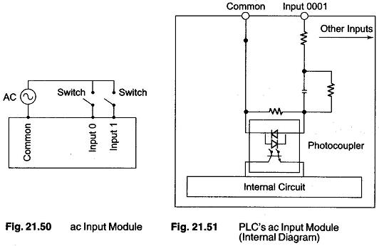
The PLC’s ac input module is as shown in Fig. 21.51. The only thing accessible to the user are the terminals labeled common, input 0000, input xxxx. The common terminal gets connected to the neutral wire.
A common switch such as limit switch, push button, toggle, etc. would be connected to the inputs directly. One side of the switch would be connected directly to input xxxx. The other end goes to the ac hot wire, assuming that the common terminal is connected to neutral.
Typically ac input takes longer than a dc input for a PLC to scan. It does not matter from the programmers point of view because an ac input device is typically a mechanical switch and mechanical devices are very slow. It is quite common for a PLC to require that the input be on for 25 or more milliseconds before it is seen. This delay is required because of the filtering which is needed by the PLC internal circuit.