AC Voltmeter using Rectifiers:
AC Voltmeter using Rectifiers – Rectifier type instruments generally use a PMMC movement along with a rectifier arrangement. Silicon diodes are preferred because of their low reverse current and high forward current ratings. Figure 4.16 (a) gives an ac voltmeter circuit consisting of a multiplier, a bridge rectifier and a PMMC movement.
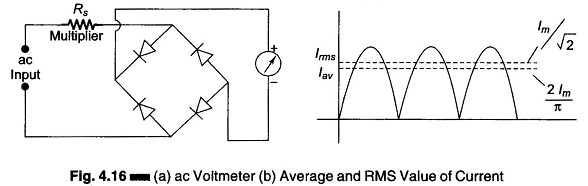
The bridge rectifier provides a full wave pulsating dc. Due to the inertia of the movable coil, the meter indicates a steady deflection proportional to the average value of the current (Fig. 4.16 (b)). The meter scale is usually calibrated to give the RMS value of an alternating sine wave input.
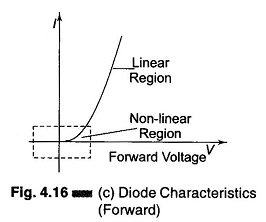
Practical rectifiers are non-linear devices particularly at low values of forward current (Fig. 4.16 (c)). Hence the meter scale is non-linear and is generally crowded at the lower end of a low range voltmeter. In this part the meter has low sensitivity because of the high forward resistance of the diode. Also, the diode resistance depends on the temperature.
The rectifier exhibits capacitance properties when reverse biased, and tends to bypass higher frequencies. The meter reading may be in error by as much as 0.5% decrease for every 1 kHz rise in frequency.
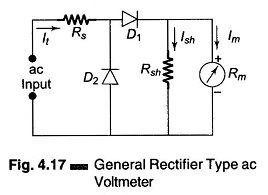
A general rectifier type ac voltmeter arrangement is given in Fig. 4.17.
Diode D1 conducts during the positive half of the input cycle and causes the meter to deflect according to the average value of this half cycle. The meter movement is shunted by a resistor, Rsh in order to draw more current through the diode D1 and move the operating point into the linear portion of the characteristic curve, In the negative half cycle, diode D2 conducts and the current through the measuring circuit, which is in an opposite direction, bypasses the meter movement.