Peak Reading AC Voltmeter Circuit:
Peak Reading AC Voltmeter Circuit : When a capacitor is connected to a sinusoidal voltage source, the charging current
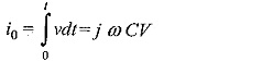
where V is the rms value of the voltage and co is the angular frequency. If a half wave rectifier is used, the arithmetic mean of the rectifier current is proportional to the peak value of the a.c. voltage. The schematic diagram of the circuit arrangement is shown in Fig. 7.15. The d.c. meter reading is proportional to the peak value of the value Vm or
![]()
where I is the d.c. current read by the meter and C is the capacitance of the capacitor. This method is known as the Chubb-Frotscue method for peak voltage measurement.
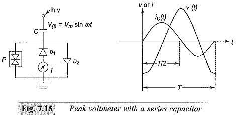
The diode D1 is used to rectify the a.c. current in one half cycle while D2 bypasses in the other half cycle. This arrangement is suitable only of positive or negative half cycles and hence is valid only when both half, cycles are symmetrical and equal. This method is not suitable when the voltage waveform is not sinusoidal but contains more than one peak or maximum as shown in Fig. 7.16. The charging current through the capacitor changes its polarity within
one of the half cycles and the current within that period subracts from the net current. Hence the reading of the meter will be less and is not proportional to Vm as the current flowing during the intervals (t1 — t2) etc. will not be included in the mean value. The second or the false maxima is easily spotted out by observing the waveform of the charging current on an oscilloscope. Under normal conditions with a.c. testing, such waveforms do not occur and as such do not give rise to errors. But pre-discharge currents within the test circuits cause very short duration voltage drops which may introduce errors. This problem can also be overcome by using a resistance R in series with capacitor C such that CR < < 1/ω for 50 Hz application.
The error due to the resistance is
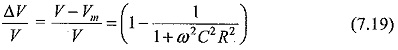
where,
V = actual value, and
Vm = measured value
In determining the error, the actual value of the angular frequency ω has to be determined.
The different sources that contribute to the error are
- the effective value of the capacitance being different from the measured value of C
- imperfect reftifiers which allows small reverse currents
- non-sinusoidal voltage waveforms with more than one peak or maxima per half cycle
- deviation of the frequency from that of the value used for calibration As such, this method in its basic form is not suitable for waveforms with more than one peak in each half cycle.
A digital peak reading meter for voltage measurements is shown in Fig. 7.17.
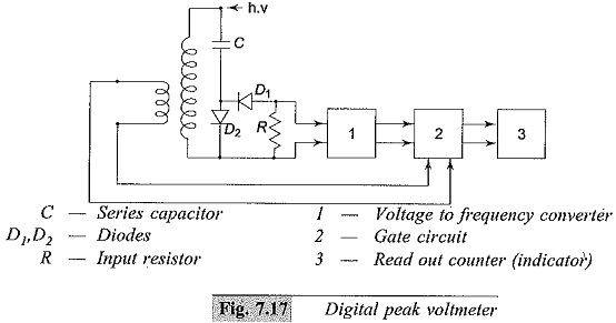
Instead of directly measuring the rectified charging current, a proportional analog voltage signal is derived which is then converted into a proportional mean frequency, fm. The frequency ratio fm/f is measured with a gate circuit controlled by the a.c. power frequency (f) and a counter that opens for an adjustable number of periods Δt =p/f During this interval, the number of impulses counted, n, is
![]()
where p is a constant of the instrument and A represents the conversion factor of the a.c. to d.c. converter.
Peak Reading AC Voltmeter Circuit with Potential Dividers:
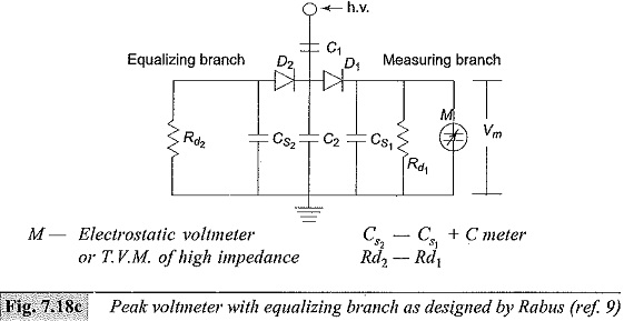
Peak Reading AC Voltmeter Circuit using capacitance dividers, designed by Bowlder et al., are shown in Fig. 7.18a. The voltage across C2 is made use of in charging the storage capacitor Cs. Rd is a discharge resistor employed to permit variation of Vm whenever V2 is reduced. Cs is charged to a voltage proportional to the peak value to be measured.
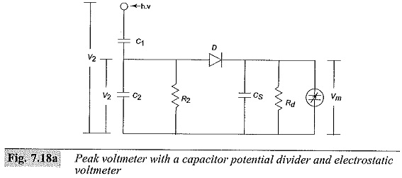
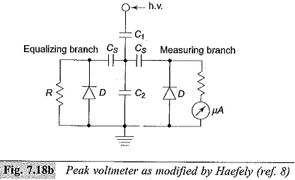
The indicating meter is either an electrostatic voltmeter or a high impedance V.T.V.M. This discharge time constant CsRd is designed to be about 1 to 10 s. This gives rise to a discharge error which depends on the frequency of the supply voltage. To compensate for the charging and discharging errors due to the resistances, the circuit is modified as shown in Fig. 7.18b. Measurement of the average peak is done by a micro ammeter. Rabus’ modification to compensate the charging errors is given in Fig. 7.18c.