Chopper type DC Amplifier Voltmeter (Microvoltmeter):
Chopper type DC Amplifier Voltmeter the dc input voltage is converted into an ac voltage, amplified by an ac amplifier and then converted back into a dc voltage proportional to the original input signal.
The balanced bridge voltmeter has limitations caused by drift problems in dc amplifier. Any fluctuations of voltage supply or variation in the `Q’ characteristics due to ageing or rise in temperature causes a change in the zero setting or balance. This drift in the steady state conditions of a dc amplifier causes the output indications to change as if the signal input had changed. This drift problem limits the minimum voltage that can be measured. To measure small voltages, a chopper type dc amplifier is used.
A chopper amplifier is normally used for the first stage of amplification in very sensitive instruments of a few μV range. In such an amplifier the dc voltage is chopped to a low frequency of 100 – 300 Hz. It is passed through a blocking capacitor, amplified and then passed through another blocking capacitor, in order to remove the dc drift or offset of the amplified signal.
The principle of operation is as given in Fig. 4.10. An ac amplifier which has a very small drift compared to a dc amplifier is used. The chopper may be mechanical or electronic. Photo diodes are used as nonmechanical choppers for modulation (conversion of dc to ac) and demodulation (conversion of ac to dc). Photo conductors have a low resistance, ranging from a few hundreds to a few thousand ohms, when they are illuminated by a neon or incandescent lamp. The photo conductor resistance increases sharply, usually to several Mega ohms when not illuminated.
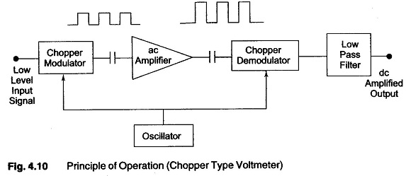
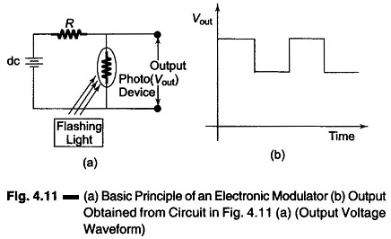
Figure 4.11 (a) shows a simple circuit for an basic principle of an electronic modulator.
A flashing light source, whose intensity varies from maximum to minimum almost instantaneously, causes the photo diode resistance to change from Rmin to Rmax quickly. Therefore the output voltage is an ac, because the photo diode has a high output when its resistance is high and a low output when its resistance is low, as shown in Fig. 4.11 (b).
In the circuit diagram of Fig. 4.12, an oscillator drives two neon lamps into illumination on alternating half cycles of oscillation. The oscillator frequency is limited to a few 100 cycles, because the transition time required for the photo diode to change from high resistance to low resistance limits the chopping range.
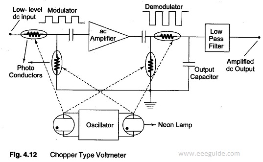
Each neon lamp illuminates one photo diode in the input circuit of the amplifier and one in the output circuit. The two photo diodes form a series shunt half wave modulator or chopper. When one photo diode or the input has maximum resistance, the other has minimum resistance. The same conditions exist at the output circuit. Together they act like a switch across the input to the amplifier, alternatively opening and closing at a rate determined by the frequency of the neon oscillator.
The input signal to the amplifier is a square wave whose amplitude is proportional to the input voltage with a frequency equal to the oscillators frequency. The ac amplifier delivers an amplified square wave at its output terminals. The photo diodes (demodulator) in the output circuit operate in anti synchronously with the input chopper, recovering the dc signal by a demodulating action. The dc output signal is then passed to a low pass filter to remove any residual ac component. This amplified drift free dc output is then applied to a PMMC movement for measurement.
The chopper eliminates the need for a high gain dc amplifier with its inherent drift and stability problems.
The input impedance of the chopper amplifier dc voltmeter is usually of the order of 10 MΩ or higher, except in low input ranges. In order to eliminate errors caused by high source impedance, an arrangement for nulling is included in the meter circuit. A control facility provided on the front panel of the instrument permits the input voltage to be nullified with a bucking voltage. When the bucking voltage is equal to the input voltage, a null is indicated, the meter exhibits infinite impedance, and therefore loading effects are totally eliminated. The input voltage is then removed and a bucking voltage equal to the input voltage is indicated by the meter.
A commercially available instrument using a photo chopper amplifier has an input impedance of 100 MΩ, a resolution of 0.1 μV and input ranges from 3 μV full scale to 1 kV full scale with an accuracy of ± 2% of full scale deflection.
Advantage of Chopper type DC Amplifier Voltmeter:
- The input impedance of a Chopper Amplifier is usually of the order of 10 MΩ or higher, except on very low input ranges.
- The drift in an ordinary dc amplifier is of the order of mV. The full scale range of an ordinary dc amplifier is limited to measuring input signal of 1 – 100 mV. In a chopper modulator system with the use of ac amplifier, drift can be cut down by a factor of 100, thus allowing an input signal range of about 0.01 mV = 10 μV full scale to be handled.