Output Power Meter Working Principle:
The Output Power Meter Working Principle is designed to directly measure the output power in an arbitrary load. The instrument provides a set of resistive loads to be selected for power measurements. In addition to power, the output power meter working principle can be used to measure impedance and frequency response characteristics. A simple circuit is illustrated in Fig. 10.1.
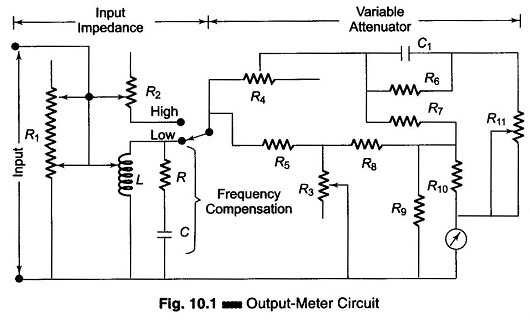
The input impedance network consist of two tapped resistances and a coil. The input impedance can be varied in steps from 2.5 Ω to 40 kΩ. At low impedance values, the coil shunts a portion of R1 – an increase in resistance results in fewer turns of the coil. This arrangement keeps the meter reading proportional to the energy dissipated by the resistor. At high impedance values, the coil is replaced by another tapped resistance R2.
The RC frequency compensator is in parallel with the coil. At low frequency, the capacitive reactance Xc is high; it decreases as frequency increases. This compensates for the losses of the coil at low frequencies. The frequency range is generally between 20 Hz and 20 kHz. R3 is the control in a variable T-network. This amounts to a variable meter shunt, which is used to extend the range of the meter. The lowest meter range is normally 5 mW, but it can be extended in decade steps of 50 mW, 500 mW, etc.
The remaining circuit of the output power meter working principle is a combination of a calibration and frequency compensation network. A meter of this type may have a midscale accuracy of ± 2% at 1 KHz. Over the frequency range of 20 Hz – 15 KHz, the accuracy may be within ± 2% of the 1 kHz value.
The input meter is subjected to an waveform error when the input is other than sinusoidal. (Practical instruments for measuring the power output of oscillators, amplifiers, transformers, transducers and low frequency lines use an input impedance of a tapped transformer with 48 impedance setting). It can be used to measure output impedance by adjusting the maximum power. It can also be used to check the frequency response characteristics of audio frequency devices.