Current transformer and Potential transformer:
These Current transformer and Potential transformer are designed to meet the specific need of measurement and instrumentation systems, which accept voltages in the range of 0-120 V and currents upto 5 A. Power system voltages can be as high as 750 kV and currents up to several tens of kA. Their measurement requires accurate ratio Current and Voltage transformations, which is accomplished by potential and current transformers.
Potential Transformer (PT):
It must transform the input voltage accurately to output voltage both in magnitude and phase. The impedance presented by the instrument on measurement system to the transformer output terminals is called burden. It is mainly resistive in nature and has a large value, e.g. the impedance (practically a resistance) of a voltmeter. The circuit model of a PT is drawn in Fig. 3.70. It is the same as that of an ordinary transformer but ideally should have
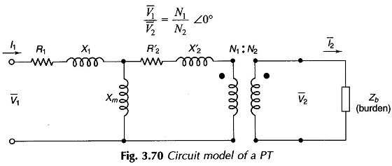
The current drawn by the burden causes a voltage drop in (R2 + j X2) and this current referred to primary plus the magnetizing current (all phasors) causes a voltage drop in (R1 + jX1). Therefore V2/V1 differs from the desired value (N1/N2) in magnitude and phase resulting in magnitude and phase errors. The errors are to be kept within the limit defined by the precision required. In order to achieve this a PT is designed and connected to have low leakage reactance, low loss and high magnetizing reactance (low magnetizing current).
Low reactance is achieved by interlacing primary and secondary both on core limb. High magnetizing reactance requires minimum iron path and high permeability steel.
Low loss requires low-loss. steel and very thin laminations. Most important thing for low PT errors is to make the burden (Zb) as high as feasible.
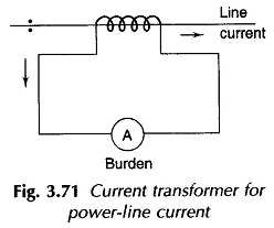
Current Transformer (CT):
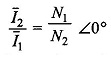
It is the current ratio transformer meant for measuring large currents and provide a step down current to current measuring instruments like an ammeter. Such instruments present a short-circuit to the CT secondary. It means that burden Zb ≈ 0. An ideal CT current ratio is
Causes of CT errors and their remedy are the same as for a PT discussed earlier in this section.
In power system applications CT has a single-turn primary which is the line itself as shown in Fig. 3.71. The secondary is rated 1-5 A.
The burden impedance (which in fact is actically resistive) cannot be allowed to exceed beyond a limit. Most important precaution in use of a CT is that in no case should it be open circuited (even accidentally). As the primary current is independent of the secondary current, all of it acts as a magnetizing current when the secondary is opened. This results in deep saturation of the core which cannot be returned to the normal state and so the CT is no longer usable