Introduction to Digital Filtering:
It has been seen that control of the band width of a circuit or signal is of paramount importance in optimizing the measurement of a signal. Formerly band width control was implemented using frequency, selective active or passive networks of resistors, capacitors and inductors. However, the results obtained were somewhat less than satisfactory, because of undesirable attenuation and phase shift of signal frequencies, resulting in distortion of signal information, or less than optimal enhancement of the signal to noise (S/N) ratio. Digital Filtering overcomes many of these problems.
Digital filtering simply involves band width control using software. A particularly powerful and informative route for the implementation of a Digital Filter is through the use of a Fourier transformation. The frequency composition can be determined from the amplitude-time waveform by carrying out a Fourier transformation. The action of an analog filter on an amplitude-time waveform can be accurately described by multiplying the frequency spectrum of the waveform by the frequency response curve for the filter.
This same process can be carried out on the computer after calculation of the Fourier transform signal waveform. However, essentially any desired frequency response curve can be set up, including many that would be simply impossible to design with hardware. Filters with no phase shift, filters with square cutoffs, high pass filters, differentiating filters and unique discrete frequency filters are all easy to implement.
A simple example is presented in Fig. 15.30. A noisy signal is shown in Fig. 15.30(a). The real output of the Fourier transform is shown in Fig. 15.30(b).
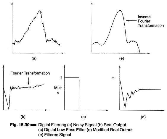
The important point is that the distribution of signal and noise information in this plot is the same as it was in the amplitude spectra with the signal information concentrated near the origin and the noise information spread throughout. A digital low pass filter is shown in Fig. 15.30(c). This filter has characteristics of no phase shift and an abrupt cutoff, which are impossible to achieve with analog filters.
Filtering is implemented by simply multiplying the real output by this filter response function, resulting in the modified real output shown in Fig. 15.30(d). The filtered signal can be regenerated by an inverse Fourier transform. The result is shown in Fig. 15.30(e). Note that the noise level has been significantly reduced. Analogous reduction of the noise level with analog techniques would have been difficult to achieve without distorting the signal information. Distortion can result from a digital filter if signal information is attenuated by the filter. Simple precautions can render such errors unlikely.
Although this example was quite simple, the basic power and flexibility of this approach to filtering should be obvious. Many unique and useful filters can be designed and implemented with this approach. It is also important to note that digital filtering as discussed in this section is exactly analogous to the moving average smoothing operations which are frequently utilized to enhance the S/N of signals.
To understand the concept of Digital Filters, the reader should be well versed in complex variables, Fourier series and Fourier transformation.