Torque Equation of DC Motor:
When dc voltage is applied to the armature of a dc motor with its field excited by dc, a torque is developed and the armature rotates. It accelerates to a speed at which the emf induced in the armature conductors balances the applied voltage and the following Torque Equation of DC Motor is satisfied.
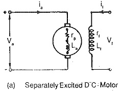
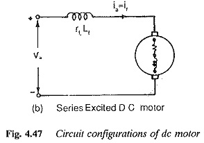
Eb is the induced emf in the armature by virtue of rotation in the uniform magnetic field at constant speed N. The nature of this emf is to oppose the terminal voltage and therefore it is also called back emf. The circuit conditions are shown in Fig. 4.47. Figure 4.47(a) depicts a separately excited motor where the excitation is provided by a current independent of Ia. Figure 4.47(b) depicts a series motor in which armature and field currents are the same. The generated voltage is given by
where
- Φ is flux per pole
- Z is number of armature conductors
- N is speed in rpm
- 2P is number of poles
- 2a is number of parallel paths in the armature
For a given DC Drives Basic Machine Equation
The Torque Equation of DC Motor developed by the armature is given by
Ka is called armature constant of the Motor.
Using Eqs 4.23 and 4.25 we have
In a separately excited motor Φ can be assumed to be constant at a given field current when armature reaction is neglected or compensated.
From eq. 4.27 it is clear that the speed of a dc motor can be varied by changing the value of (Va – Iara).
Torque Equation of DC Motor is normally is achieved in two ways:
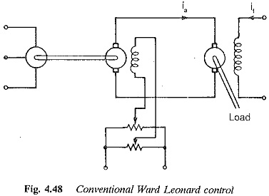
- By varying the value of applied voltage to the armature, as is done in Ward Leonard system (Fig. 4.48).
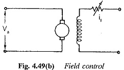
- By inserting an extra resistance in series with the armature (Fig. 4.49).
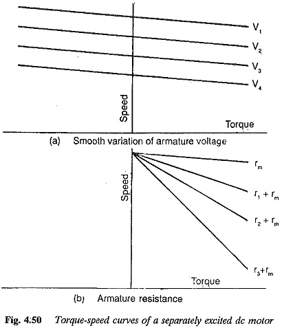
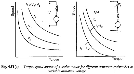
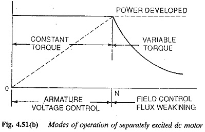
In the former, a variable voltage supply is required. The operation is loss free and efficient. The Torque Equation of DC Motor versus speed characteristic is shown in Fig. 4.50. In the latter, extra resistance inserted involves extra losses and the motor becomes less efficient. The Speed Torque Equation of DC Motor characteristic is shown in Fig. 4.51. In both the cases very small speeds up to zero speed are possible. The motor operates at constant torque from zero to base speed.
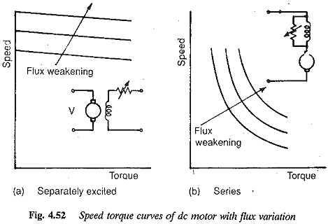
The speed of a dc Motor is also varied by variation of field flux. Speeds above base speeds are possible in this method of control. This method is suitable for variable torque loads.
Speed control by means of a variable voltage is very efficient. This variable voltage is obtained from a generator. The method is known as the Ward Leonard method. It is very versatile and has the following features:
- The motor can be accelerated at constant torque (constant armature current) by suitably adjusting the field of the motor.
- The regenerative braking of the motor is possible and the motor can be brought to rest very fast.
- Four quadrant operation of the motor is straightforward.
- The capital cost is more, as an extra M G set is required.
- The equipment requires space.
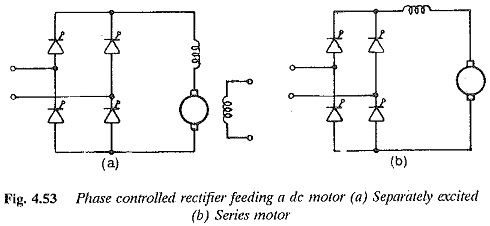
The advent of thyristors and the development of power converters using thyristors has made the speed control of electric motors easier and more straightforward. Phase controlled rectifiers provide a variable dc voltage to the armature of a dc motor (Fig. 4.53). These converters can also operate as inverters, in which case regenerative braking of the dc motor is possible. By suitable connection of these converters, a reversible drive allowing motoring and regeneration in both the directions of rotation is possible. These converters are more flexible, have a faster response and occupy less space. A static Ward Leonard system can be made possible using these converters. However, there are certain drawbacks, such as poor power factor on the ac side due to lagging current, non-sinusoidal input current having rich harmonic content, etc. The load voltage is superimposed by a ripple content. The load current also has a ripple making the ratios of peak to average current and rms to average current greater than one. A large inductance is required on the load side to smoothen the current. Sometimes the load current is discontinuous, which reduces the performance. The ripple content affects the motor heating and commutation. Therefore it is necessary to develop the rectifier which provides a supply to the motor causing only very little variations in the performance as compared to a normal dc supply. Sometimes the dc motor design is modified so that it can be used on any converter.
A dc motor on normal dc supply requires a starting resistor to limit the starting current. When fed from a thyristor converter the starting resistance can be dispensed with and soft starting is possible. The motor can be accelerated at constant torque.
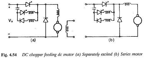
The dc chopper can be interposed between dc mains of fixed voltage and the dc motor provide a variable voltage to the motor to control the speed. Regeneration is possible in this case also. A static Ward Leonard scheme is possible for two and four-quadrant operation. The output voltage of the chopper is in the form of pulses. The time ratio of the chopper can be controlled to vary the average voltage. The output current varies exponentially during TON and TOFF of the chopper. The output current varies between two limits. There is a possibility of discontinuous conduction if the ripple is more and the load current is small. The chopper can also be controlled with specified current limits, the method being known as current limit control. This fixes the chopper frequency. The ripple content can be limited by proper choice of the limits. The current limit control is less prone to discontinuous conduction. The increased chopper frequency introduces losses. Soft starting and acceleration are possible. Since the battery is supplying the power the problems of harmonic content and power factor are absent.
The performance of a dc motor when operating on phase controlled converters or dc choppers differs very much from the performance when operating on a normal dc supply. The ripple content of the load current affects the motor performance, whereas the harmonics and poor power factor affect the line performance. An understanding of the behavior helps in improving either the converter or motor design, to achieve better performance.

