Introduction of DC Motor:
Introduction of DC Motor is constructed in many forms and for a variety of purposes, from the 3-mm stepper drawing a few μA at 1.5 V in a quartz crystal watch to the giant 75000-kW or more rolling mill motor. It is a highly versatile and flexible machine. It can satisfy the demands of load requiring high starting, accelerating and retarding torques. A dc machine is also easily adaptable for drives with a wide range of speed control and fast reversals.
DC motors are used in rolling mills, in traction and in overhead cranes. They are also employed in many control applications as actuators and as speed or position sensors. With ac being universally adopted for generation, transmission and distribution, there are almost no practical uses now of the dc machine as a power generator. Its use as a motor-generator (ac motor-dc generator) for feeding dc drives has also been replaced in modem practice by rectifier units. In certain applications dc motors act as generators for brief time periods in the “regenerative” or “dynamic braking” mode, especially in electric traction systems.
Cross Sectional View of DC Machine:
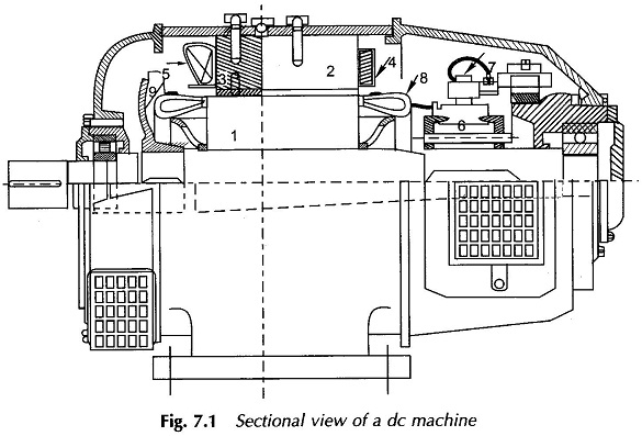
The basic principles underlying the operation and constructional features of a introduction of DC Motor and the emf equation was already discussed. It was stated there that the field winding (concentrated type) is mounted on salient-poles on the stator and the armature winding (distributed type) is wound in slots on a cylindrical rotor. Constructional features of a practical machine are brought out by half cross sectional view of dc machine of Figs 7.1 and 7.2 wherein all important machine parts are named. Both small and large industrial machines have generally the conventional heteropolar cylindrical rotor structure, although some unconventional homopolar machines have also been devised.
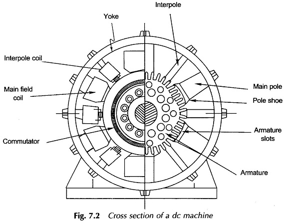
The magnetic circuit of a dc machine consists of the armature magnetic material (core), the air-gap, field poles and yoke as shown in Figs 7.2. The yoke of a dc machine is an annular ring to the middle of which are bolted field poles and the interpoles. The interpoles or commutation poles are narrow poles fixed to the yoke, midway between the main field poles. Interpoles and compensating windings, which will be described later in this chapter in connection with commutation problems, are required to be excited suitably.
The use of an electric field winding, which supplies electric energy to establish a magnetic field in the magnetic circuit, results in the great diversity and a variety of performance characteristics. The armature winding is connected to the external power source through a commutator-brush system (see Fig. 7.1 item 6), which is a mechanical rectifying (switching) device for converting the alternating currents and induced emfs of the armature to dc form. The longitudinal and perpendicular to the machine axis cross-sectional view of a dc machine, indicating the location and nomenclature of machine parts are presented in Figs 7.1 and 7.2.
The cylindrical-rotor or armature of a dc machine is mounted on a shaft which is supported on the bearings. One or both ends of the shaft act as input/output terminal of the machine and would be coupled mechanically to a load (motoring machine) or to a prime-mover (generating machine). Usually parallel-sided axial slots (evenly spaced normally) are used on the rotor surface. In these slots armature coils are laid as per winding rules. The magnetic material between slots are the teeth. The slot cross-section influences significantly the performance characteristics of the machine and parameters such as armature coil inductance, magnetic saturation in teeth, eddy-current loss in the stator poles and the cost and complexity of laying armature winding.
The design of electrical machines has become a very interesting and challenging topic and is continuously changing with new and improved magnetic, electrical and insulating materials, the use of improved heat-transfer techniques, development of new manufacturing processes and the use of computers. There are full-fledged excellent texts [9, 46] dealing with the design aspects. The objective of this chapter is to analyse the behavior and Introduction of DC Machine in detail and present the physical concepts regarding its steady-state performance.
Observations in DC Motor:
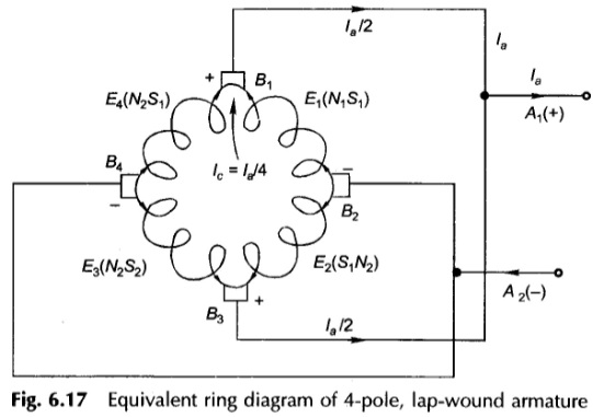
The operational aspects of a dc-like nature of emf and current distribution in conductor around the armature and commutation have been discussed in early topics. This is explained in the lap winding (developed) diagram of Fig. 6.16 and equivalent ring diagram of Fig. 6.17. From this discussion certain observations about the Introduction of DC Motor are summarized as follows. These will help in visualizing the machine behavior.
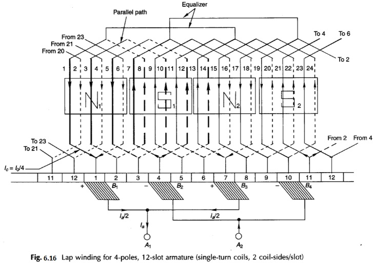
- Brushes in a dc machine are normally placed electrically in the inter polar regions and therefore make an angle of 90° elect. with the axes of the adjoining field poles.
- A lap winding has A = P parallel paths such that the armature current Ia divides out into A paths giving a conductor current of Ic = Ia/A. In the case of wave winding, A = 2, independent of P.
- The brushes are alternately positive and negative (elect. angle between adjacent pair being 180° elect). Only two brushes are needed in wave winding though P brushes are commonly provided for heavy-current armatures.
- The armature periphery is divided into “belts” (P in number) each under influence of a pole. Emfs and currents in all the conductors of a belt are unidirectional—conductors that go out of a belt due to rotation are simultaneously replaced by an equal number coming into the belt. Magnitude of conductor emfs in a belt follows the pattern (wave) of flux density in the air-gap while the current in all these conductors (Ic) is the same in all the belts except that the current pattern in the belts alternate in space but remain fixed in time. This basically results from the action of the commutator.
- If the conductor current flows in the same direction as the conductor emf, the machine outputs electrical power (and absorbs mechanical power), i.e. the machine is operating in generating mode. On the other hand, when the conductor current and emf oppose each other, the machine absorbs electrical power and outputs mechanical power, i.e. it operates in the motoring mode.
- Barring irrecoverable losses (of both electric and magnetic origin), there is a balance between electrical and mechanical powers of the machine; the average energy stored in the magnetic field remains constant independent of the armature rotation.