Series Type Ohmmeter:
Series Type Ohmmeter – A D’ Arsonval movement is connected in series with a resistance R1 and a battery which is connected to a pair of terminals A and B, across which the unknown resistance is connected. This forms the basic type of series ohmmeter, as shown in Fig. 4.28 (a).
The current flowing through the movement then depends on the magnitude of the unknown resistance. Therefore, the meter deflection is directly proportional to the value of the unknown resistance.
Referring to Fig. 4.28 (a)
- R1 = current limiting resistance
- R2 = zero adjust resistance
- V = battery
- Rm = meter resistance
- RX = unknown resistance
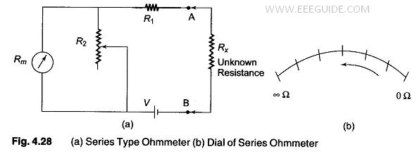
Calibration of the Series Type Ohmmeter:
To mark the “0” reading on the scale, the terminals A and B are shorted, i.e. the unknown resistance Rx = 0, maximum current flows in the circuit and the shunt resistance R2 is adjusted until the movement indicates full scale current (Ifsd). The position of the pointer on the scale is then marked “0” ohms.
Similarly, to mark the “∞” reading on the scale, terminals A and B are open, i.e. the unknown resistance Rx = ∞, no current flow in the circuit and there is no deflection of the pointer. The position of the pointer on the scale, is then marked as “∞” ohms.
By connecting different known values of the unknown resistance to terminals A and B, intermediate markings can be done on the scale. The accuracy of the instrument can be checked by measuring different values of standard resistance, i.e. the tolerance of the calibrated resistance, and noting the readings.
A major drawback in the series ohmmeter is the decrease in voltage of the internal battery with time and age. Due to this, the full scale deflection current drops and the meter does not read “0” when A and B are shorted. The variable shunt resistor R2 across the movement is adjusted to counteract the drop in battery voltage, thereby bringing the pointer back to “0” ohms on the scale.
It is also possible to adjust the full scale deflection current without the shunt R2 in the circuit, by varying the value of R1 to compensate for the voltage drop. Since this affects the calibration of the scale, varying by R2 is much better solution. The internal resistance of the coil Rm is very low compared to R1. When R2 is varied, the current through the movement is increased and the current through R2 is reduced, thereby bringing the pointer to the full scale deflection position.
The series ohmmeter is a simple and popular design, and is used extensively for general service work.
Therefore, in a series ohmmeter the scale marking on the dial, has “0” on the right side, corresponding to full scale deflection current, and “∞” on the left side corresponding to no current flow, as given in Fig. 4.28 (b).
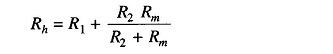
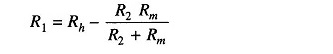
Values of R1 and R2 can be determined from the value of Rx which gives half the full scale deflection.
where
- Rh = half of full scale deflection resistance.
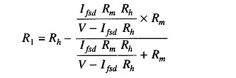
The total resistance presented to the battery then equals 2Rh and the battery current needed to supply half scale deflection is Ih = V/2 Rh..
To produce full scale current, the battery current must be doubled.
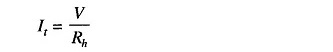
Therefore, the total current of the ckt, It = V/Rh
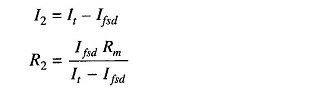
The shunt current through R2 is given by I2 = It – Ifsd
The voltage across shunt, Vsh, is equal to the voltage across the meter.
Therefore
Therefore
But
But
Therefore
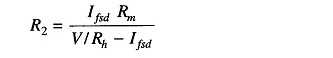
Therefore
As
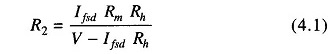
Therefore
Hence
Therefore
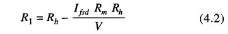
Hence, R1 and R2 can be determined.