Types of Facts Controllers in Power System:
The development of FACTS controllers has followed two different approaches. The first approach employs reactive impedances or a tap changing transformer with thyristor switches as controlled elements, the second approach employs self-commutated static converters as controlled voltage sources. In general, Various types of facts controllers in power system are
- series controllers
- shunt controllers
- combined series-series controllers
- combined series-shunt controllers.
The general symbol for a types of facts Controllers is given in Fig. 15.8(a). which shows a thyristor arrow inside a box. The series controller of Fig. 15.8b could be a variable impedance, such as capacitor, reactor, etc. or a power electronics based variable source. All series controllers inject voltage in series with the line. If the voltage is in phase quadrature with the line, the series controller only supplies or consumes variable reactive power. Any other phase relationship will involve real power also.
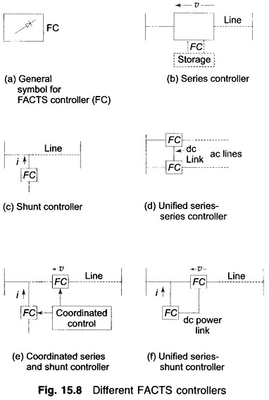
The shunt controllers of Fig. 15.8c may be variable impedance, variable source or a combination of these. All shunt controllers inject current into the system at the point of connection. Combined series-series controllers of Fig. 15.8d could be a combination of separate series controllers which are controlled in a coordinated manner or it could be a unified controller.
Combined series-shunt controllers are either controlled in a coordinated manner as in Fig. 15.8e or a unified Power Flow Controller with series and shunt elements as in Fig. 15.8f. For unified controller, there can be a real power exchange between the series and shunt controllers via the dc power link.
Storage source such as a capacitor, battery, superconducting magnet, or any other source of energy can be added in parallel through an electronic interface to replenish the converter’s dc storage as shown dotted in Fig. 15.8 (b). A controller with storage is much more effective for controlling the system dynamics than the corresponding controller without storage.
The group of FACTS controllers employing switching converter-based synchronous voltage sources include the STATic synchronous COMpensator (STATCOM), the static synchronous series compensator (SSCC), the unified power flow controller (UPFC) and the latest, the Interline Power Flow Controller (IPFC).
STATCOM
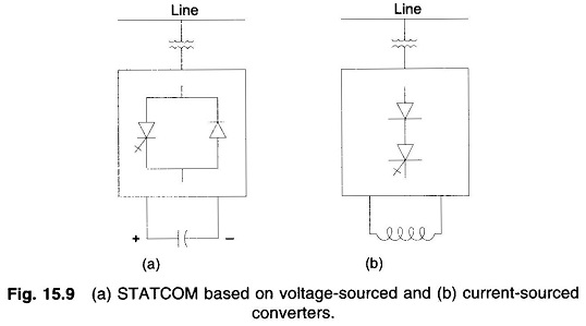
STATCOM is a static synchronous generator operated as a shunt-connected static var compensator whose capacitive or inductive output current can be controlled independent of the ac system voltage. The STATCOM, like its conventional counterpart, the SVC, controls transmission voltage by reactive shunt compensation. It can be based on a voltage-sourced or current-sourced converter. Figure 15.9 shows a one-line diagram of STATCOM based on a voltage-sourced converter and a current sourced converter. Normally a voltage-source converter is preferred for most converter-based FACTS controllers. STATCOM can be designed to be an active filter to absorb system harmonics.
A combination of STATCOM and any energy source to supply or absorb power is called static synchronous generator (SSG). Energy source may be a battery, flywheel, superconducting magnet, large dc storage capacitor, another rectifier/inverter etc.
Static Synchronous Series Compensator (SSCC)
It is a series connected controller. Though it is like STATCOM, but its output voltage is in series with the line. It thus controls the voltage across the line and hence its impedance.
Interline Power Flow Controller (IPFC)
This is a recently introduced controller. It is a combination of two or more static synchronous series compensators which are coupled via a common dc link to facilitate bi-directional flow of real power between the ac terminals of the SSSCs, and are controlled to provide independent reactive series compensation for the control of real power flow in each line and maintain the desired distribution of reactive power flow among the lines. Thus it manages a comprehensive overall real and reactive power management for a multi-line transmission system.
Unified Power Flow Controller (UPFC)
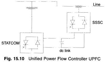
This controller is connected as shown in Fig. 15.10. It is a combination of STATCOM and SSSC which are coupled via a common dc link to allow bi-directional flow of real power between the series output terminals of the SSSC and the shunt output terminals of the STATCOM. These are controlled to provide concurrent real and reactive series line compensation without an external energy source. The UPFC, by means of angularly unconstrained series voltage injection, is able to control, concurrently/simultaneously or selectively, the transmission line voltage, impedance, and angle or, alternatively, the real and reactive line flows. The UPFC may also provide independently controllable shunt reactive compensation.
Thyristor-Controlled Phase-Shifting Transformer (TCPST)
This controller is also called Thyristor-controlled Phase Angle Regulator (TCPAR). A phase shifting transformer controlled by thyristor switches to give a rapidly variable phase angle.
Thyristor-Controlled Voltage Regulator (TCVR)
A thyristor controlled transformer which can provide variable in-phase voltage with continuous control.
Interphase Power Controller (IPC)
A series-connected controller of active and reactive power consisting, in each phase, of inductive and capacitive branches subjected to separately phase-shifted voltages. The active and reactive power can be set inpedendently by adjusting the phase shifts and/or the branch impedances, using mechanical or electronic switches.
Thyristor Controlled Braking Resistor (TCBR)
It is a shunt-connected thyristor-switched resistor, which is controlled to aid stabilization of a power system or to minimise power acceleration of a generating unit during a disturbance.
Thyristor-controlled Voltage Limiter (TCVL)
A thyristor-switched metal-oxide varistor (MOV) used to limit the voltage across its terminals during transient conditions.
HVDC
It may be noted that normally HVDC and FACTS are complementary technologies. The role of HVDC, for economic reasons, is to interconnect ac systems where a reliable ac interconnection would be too expensive. HVDC transmission as well as back-to-back HVDC system can improve transient stability and control line flows. Voltage source converter based (self-commutated) HVDC system may have the same features as those of STATCOM or UPFC. This system also regulates voltage and provides system damping.
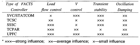
A comparative performance of major types of facts Controllers in ac system is given in Table 15.2.