Magnetic Flow Meters:
Magnetic Flow Meters are the first type of flowmeters to be considered for high corrosive applications and for applications involving measurement of erosive slurries. These meters work on the principle of Faraday’s law of electromagnetic induction, which states that whenever a conductor moves through a magnetic field of given field strength, a voltage is induced in the conductor proportional to the relative velocity between the conductor and the magnetic field. This concept is used in electric generators. In case of flowmeters, electrically conductive flowing liquids work as the other conductor.
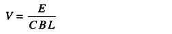
The induced voltage is given by the equation
![]()
where
- E = Induced voltage in volts
- C = Dimensional constants
- B = Magnetic flux in Wb/sq.m
- L = Length of the conductor (fluid) in m
- V = Velocity of the conductor (fluid) in m/s
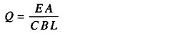
The equation to convert a velocity measurement to volumetric flow rate is
![]()
where
- Q = Volumetric flow rate
- V = Fluid velocity
- A = Cross-sectional area of the flowmeter
From (13.17)
Therefore
For a given flowmeter, A, C, B, L are constants.
Therefore
![]()
where
![]()
Therefore the induced voltage is directly proportional and linear to the volumetric flow rate.
Construction of Magnetic Flow Meter:
The Magnetic Flow Meters consists of an electrically insulated or non conducting pipe, such as fibre glass, with a pair of electrodes mounted opposite each other and flush with the inside walls of the pipe, and with the magnetic coil mounted around the pipe so that a magnetic field is generated in a plane mutually perpendicular to the axis of the flow meter body and to the plane of the electrodes.
If a metal pipe is used, an electrically insulating liner is provided on the inside of the pipe.
Working Principle of Magnetic Flow Meter:
The basic operating principle of a Magnetic Flow Meters in which the flowing liquid acts as a conductor is shown in Fig. 13.59.
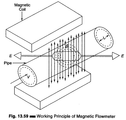
The length L is the distance between the electrodes and equals the pipe diameter. As liquid passes through the pipe section, it also passes through the magnetic field set up by the magnet coils, thus inducing a voltage in the liquid, which is detected by a pair of electrodes mounted on the pipe wall. The amplitude of the induced voltage is proportional to the velocity of the flowing liquid. The magnetic coils may be excited by either ac or dc voltage. Currently, pulsating dc in which magnetic coils are periodically energized is used.
Magnetic Flow meters are available in sizes from 2.54 – 2540 mm in diameter, with an accuracy range of ± 0.5 to ± 2%. The measurement taken by these meters are independent of viscosity, density, temperature and pressure. (The range of such meters may be 30:1, but normally a 20:1 range is accepted.)
A modern design of Magnetic Flow Meter is one which can be inserted into the line through couplings. It consists of electrodes mounted on each side of a probe and magnetic coils which are also integral to the probe. The probe can be mounted on pipes of diameters 152.4 mm and above can easily be mounted for open channel flow.
Advantages of Magnetic Flow meter:
- It can handle slurries and greasy materials.
- It can handle corrosive fluids.
- It has very low pressure drop.
- It is totally obstruction less.
- It is available in large pipe sizes and capacity as well as in several construction materials.
- It is capable of handling low flows (with minimum size less than 3.175 mm inside diameter) and very high volume flow rate (with sizes as large as 3.04 m).
- It can be used as bidirectional meter.
Disadvantage of Magnetic Flow meter:
- It is relatively expensive.
- It works only with fluids which are adequate electrical conductors.
- It is relatively heavy, especially in larger sizes.
- It must be full at all times.
- It must be explosion proof when installed in hazardous electrical areas.