Power Flow Studies Interview Questions and Answers:
1. What is the purpose served by power flow analysis ?
Ans. Power flow analysis provides a systematic mathematical approach for determination of various bus voltages, their phase angles, active and reactive power flows through different branches, generators and loads under steady state conditions.
2. Name the three categories of buses.
Ans. Depending upon which quantities have been specified, the buses are classified into following three categories;
- Generation or voltage-controlled or P-V buses,
- Load or P-Q buses and
- Slack or swing or reference bus.
3. What are quantities specified at a generator bus ?
Ans. At a generator bus voltage magnitude and true or active power are specified.
4. Mention the items specified and not specified at a reference bus.
Ans. At a reference bus, the magnitude and phase angle of the voltage are specified. The unknown quantities are active and reactive power flows.
5. Distinguish between voltage control bus and swing bus.
Ans. Voltage-Controlled Bus. This is also called the P-V bus, and on this bus the voltage magnitude corresponding to generation voltage and true or active power P corresponding to its ratings are specified. Voltage magnitude is maintained constant at a specified value by injection of reactive power. The reactive power generation Q and phase angle δ of the voltage are to be computed.
Slack, Swing or Reference Bus. One of the generation buses in a power system is chosen as slack or swing bus. At this bus, the magnitude and phase angle of the voltage are specified. The phase angle of the voltage is usually set equal to zero. The active and reactive powers at this bus are to be determined through the solution of equations. The swing bus is a fictitious concept in load flow studies and arises because the I2R losses of the system are not known precisely in advance for the load flow calculations. Therefore, the total injected power cannot be specified at every single bus. At the swing bus, it is customary to regard the active power as unknown. The difference between the expected and solved output (MW) represents the error in the prior estimate of system I2R losses. The generators at the swing bus supply the difference of the specified active power to be injected into the system at other buses and the total system output plus losses. If slack bus is not specified, the generation bus usually with maximum active power P is taken as reference bus. There can be more than one slack bus in a given network.
6. Why is one of the buses taken as slack bus in load flow studies ?
Ans. In a power system, there are mainly two types of buses viz. load and generator buses. For these buses, we have to specify real power P injections, which is positive for generator buses and negative for load buses. The losses remain unknown until the load flow solution is complete. Because of this, one of the generator buses is made to take the additional power to supply transmission losses. This bus is called the slack or swing bus. At this bus, the magnitude and phase angle of the voltage are specified and the active and reactive powers are to be determined through the solution of the equations.
7. What is necessity of designating one of the bus as a slack bus ?
Ans. The need to designate one of the buses as a slack bus is obviously due to the fact that the system power losses are not known initially and, therefore, the net power flow into the system cannot be fixed in advance.
8. What are the guidelines for choosing slack bus ?
Ans. One of the generation bus is selected as slack bus and the generators at this bus supply the difference between the specified real power injected into the system at other buses and the total output of the system plus system power losses.
9. Define the bus admittance matrix.
Ans. General equation for n-bus network based on Kirchhoff’s current law and admittance form is [I] = [Ybus] * [V] where [I] is the n-bus current matrix, [V] is the n-bus voltage matrix and [Ybus] is called the bus-admittance matrix and above equation is written as I = Ybus V
where
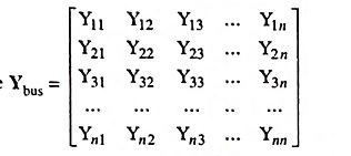
and is called the bus admittance matrix.
10. Define tree, co-tree and cut-set.
Ans.
- Tree is a subgraph containing all the nodes of the original graph but no closed path. The elements of the tree are known as branches.
- Co-tree is a complement of a tree. The elements of the original graph not included in the tree, form a subgraph which may not necessarily be connected, is known as co-tree.
- Cut-set is the minimal set of the elements in the connected graph which when removed, divide the graph in only two parts, i.e., two connected subgraphs.
11. Give any two operating constraints imposed in load flow studies.
Ans. Two operating constraints may be voltage and reactive power.
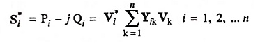
12. Write general expression for the complex power injected by the source into the ith bus of a power system.
Ans. General expression for the complex power (conjugate) injected into ith bus is given as
13. Name any two iterative methods used for solution of load flow problems.
Ans. The most commonly used iterative methods for solution of load flow problems are 1. Gauss-Seidel method and Newton-Raphson method.
14. Write Gauss-Siedel Iterative formula for solving flow equations.
Ans. Gauss-Seidel load flow formula is given as
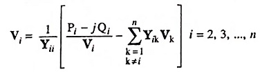
Bus 1 is a slack bus with specified V.
15. What is meant by acceleration factor in load flow solution and its best value ?
Ans. Acceleration factor is used in Gauss-Seidel method of load flow solution to increase the rate of convergence. Acceleration factor = 1.6 is considered to be a good value for power flow studies.
16. Why an acceleration factor is commonly used in load flow studies using G-S method ?
Ans. In the Gauss-Seidel method, a large number of iterations are required to arrive at the specified (desired) convergence. The rate of convergence can be significantly increased by using accelerating factor to the solution obtained after each iteration. The acceleration factor is a multiplier that enhances correction between the values of voltage in two successive iterations.
If Δx(r) and Δy(r) indicate the variable change in the (r – 1)th and rth iteration, the difference variables can be written as:
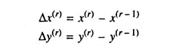
If the difference is multiplied by the acceleration factor α which is larger than unity (usually between 1.5 and 1.7 for the solution of power flow equations), the accelerated iterates are obtained as follows:
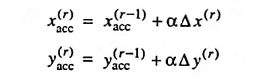
The accelerated values of x and y are used in the iteration process instead of x, y.
17. Why is Gauss-Seidel method considered superior to Gauss-iterative method ?
Ans. The Gauss-Seidel method uses upgraded iterates as soon as they are available and thus has an advantage over the Gauss-iterative method which takes longer time. Gauss-Seidel method converges much faster than the Gauss-iterative method, i.e., the number of iterations required to obtain the solution is much less in Gauss-Seidel method compared to the Gauss-iterative method.
18. Which method out of Gauss-Seidel method and Newton-Raphson method is used for large power system ?
Ans. Newton-Raphson method as it needs less number of iterations to reach convergence, takes less computer time, convergence is certain, computer cost is less and it is more accurate and is insensitive to factors like slack bus selection, regulating transformer etc.