Power Converters Interview Questions and Answers:
1. What is freewheeling diode?
Ans. Freewheeling diode is a bypass or commutating diode. It is connected across motor terminals to allow for dissipation of energy stored in motor inductance and to provide for continuity of motor current when the thyristors are blocked. It also provides protection against transient overvoltages.
2. What is the relationship of Vdc and Vac in terms of firing angle α for half-controlled and full-controlled converters?
Ans.
For half-controlled converter,
![]()
For full-controlled converter,

3. What are the drawbacks of half-wave rectifier circuits?
Ans. The output voltage wave of a half-wave rectifier is not a perfect dc. It is a discontinuous current and contains various harmonics. So half-wave converter drives have poor performance and their use is limited to small drives (rating upto 500 W).
4. What is the necessity of dc choke coil and freewheeling diode in a converter circuit?
Ans. Freewheeling diode allows for dissipation of energy stored in the motor inductance and dc choke coil reduces the rate of decay of current during the freewheeling operation when thyristors are blocked and thus motor current is made continuous. Discontinuous armature current results in deterioration
5. Why input power factor of a single-phase half-controlled bridge rectifier is higher than that for a fully controlled bridge rectifier supplying an R-L load for the same firing angle?
Ans. In a single-phase full bridge rectifier, during the interval π to (π + α) or (π to β), ‘Vs‘ in negative and ‘Is‘ is positive and therefore, energy stored in inductance L is returned to the supply resulting in decrease in power delivered to load. But in case of 1-Φ half controlled rectifier energy stored in inductance L is delivered to the load through the FWD.
So, input power factor for a fully-controlled bridge rectifier will be lower than that of 1-Φ half-controlled bridge rectifier
6. Adding an inductance L in series and a freewheeling diode (FWD) in parallel to the load circuit of an SCR converter has several advantages. Enumerate the advantages of the load inductance and freewheeling diode.
Ans. Since current through an inductance L cannot change instantaneously, an inductance L in series with the load circuit does not permit the load current to fall to zero and thus avoids the discontinuous operation of the SCR converter. Use of inductance of very high value results into almost constant and ripple free load current.
The use of freewheeling diode across the load circuit provides the following advantages:
(i) Improvement of input power factor (ii) Improvement of load current waveform resulting in better performance of load (iii) Preventing of load voltage Vout from becoming negative and (iv) Improvement in overall efficiency of converter because energy stored in inductance L is transferred to load during freewheeling period.
7. Why three-phase half-wave drives are generally not employed in industrial applications ?
Ans. Because of presence of dc component in supply currents.
8. Semiconverter system is preferred for dc series motor drive. Why?
Ans. The semiconverter system, because of its freewheeling action helps in maintaining continuous current and thus provides better performance to dc series motors in comparison to full converter system.
9. What is a chopper?
Ans. A chopper is a static switch to provide variable dc voltage from a source of constant dc voltage source.
10. Give the applications of dc choppers.
Ans. DC choppers are employed in trolley cars, marine hoists, forklift trucks, mine haulers and electric traction.
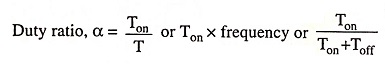
11. What is meant by duty ratio of a dc chopper?
Ans. The ratio of on-period to the time period is known as duty ratio, i.e.,
12. What are the advantages of chopper fed drive over converter fed drive?
Ans. The advantages of chopper fed drive over converter fed drive are:
- The ripple in the output of chopper is much less than that in the output of a converter. Lesser ripple means lesser losses.
- The chances of discontinuous operation in chopper drive are lesser than that in converter drive. So speed regulation and transient response of chopper drive are better than that in converter drive.
13. Enumerate the control strategies used in dc choppers.
Ans. There are two types of control strategies for operating the switches that can be used in dc choppers. These control strategies are time ratio control (TRC) and current limit control.
14. What is TRC? In how many ways can it be affected?
Ans. TRC (time-ratio control) is a control strategy in which the value of Ton/T is varied. This is affected in two ways namely variable frequency control (FM control) and constant frequency control (PWM).
15. What quantity is varied in PWM and frequency modulation ?
Ans. In pulse width modulation (PWM), the chopping period T is kept constant but the pulse width Ton is varied to control the output.
In frequency modulation the chopping frequency is varied and for this purpose either Ton or Toff is varied.
16. What is a step-up chopper?
Ans. A step-up chopper, like a step-up transformer, raises the level of input dc voltage.
17. On what principle does a step-up chopper operate?
Ans. A step-up chopper operates on the principle of storing energy in an inductance to provide output voltage higher than source voltage.
18. What is steady-state ripple?
Ans. When chopper feeds R-L or R-L-Eb load, the current varies between Imax and Imin. The difference of Imax and Imin is known as steady-state ripple.
19. When is steady-state ripple maximum.
Ans. When α = 0.5, steady-state ripple is maximum.
20. What factors can make the current discontinuous in a chopper feeding an R-L-Eb load?
Ans. Higher L/R ratio, low duty cycle and higher back emf can make the current discontinuous.
21. Why are ac regulators preferred over conventional methods of providing ac variable voltage of constant frequency for ac motor drives?
Ans. AC regulators using thyristors are becoming popular because of high efficiency, fast control and compact size.
22. What is difference between on-off control and phase control in the case of ac voltage controller?
Ans. In on-off control, also known as integral cycle control, the thyristors are used to connect the motor to the supply source for a certain number of cycles and then to disconnect it for another certain number of cycles; each of the on and off times consist of an integral number of cycles. On the other hand in phase control, the thyristors are employed as switches for connecting the motor to the supply for a certain portion of each cycle of the supply voltage.
23. Mention any two drawbacks of cycloconverters.
Ans. The two drawbacks of cycloconverters are :
- It needs more power semiconductors than an inverter.
- They can produce only a sub-frequency output.
24. Give some applications of cycloconverter.
Ans. Cycloconverter drives are normally used for large sized motors. They have also been employed in gearless cement mill or ball mill drives.
25. What is an inverter? Is it used in small power applications or high power applications or both?
Ans. A device that converts dc power into ac power of desired output voltage and frequency is known as an inverter. It is used in both of small as well as high power applications.
26. Enlist a few industrial applications of inverters.
Ans. Some industrial applications of inverters are for adjustable-speed ac drives, induction heating, standby aircraft power supplies. One of the biggest applications of inverters is in HVDC power transmission.
27. Give the classification of inverters.
Ans. Inverters are classified as single-phase or three-phase, voltage source or current source and series or parallel or bridge inverters.
28. Why bridge circuits are very popular for inverter operation ?
Ans. Bridge circuits are very popular for inverter operation because bridge circuits do not require output transformer and can be easily extended for multi-phase operation.
29. What is the difference between single-phase half-bridge circuits and full-bridge circuits?
Ans. Single-phase half-bridge inverter circuit needs two thyristors and two diodes while full-bridge inverter circuit needs four thyristors and four diodes. The main drawback of half-bridge inverter is that it requires 3-wire dc supply which is overcome in full-bridge rectifier.
30. For providing adjustable-frequency power to industrial applications, three-phase inverters are more common than single phase inverters. Why?
Ans. Three single-phase inverters connected in parallel provides a 3-phase operation. The gating signals for the three inverters have a phase difference of 120°. This arrangement requires 3 single-phase transformers, 12 thyristors and 12 diodes (i.e. 1 transformer, 4 thyristors and 4 diodes for each phase) while a 3-phase inverter needs only 6 thyristors and 6 diodes. This is the reason that three-phase inverters are more common than single phase inverters for providing adjustable frequency power to industrial applications.
31. What are the two modes of operation of 3-phase inverters?
Ans. Two modes of operation of 3-phase inverters are 120° conduction mode and 180° conduction mode. In 120° conduction mode, each thyristor conducts for 120° while in 180° conduction mode, each thyristor conducts for 180°. But in both modes of operation gating signals are applied and removed at 60° intervals of the output voltage waveform.
32. Compare the two modes of operation of 3-phase inverters.
Ans. Two modes of operation of 3-phase inverters are 120° conduction mode and 180° conduction mode. 120° conduction mode is more reliable and the possibility of two series thyristors conducting simultaneously is very much reduced but 180° conduction scheme has utilization factor more than that with 120° conduction.
33. What is the need for controlling the output voltage of an inverter?
Ans. The variation and control of output voltage is required for the following reasons :
- To compensate for change in input dc voltage.
- To compensate for voltage drop in the thyristors, diodes and other components of inverter circuit.
- To run variable speed drives. The variation in speed is achieved by variation of voltage.
34. What is pulse-width modulation?
Ans. PWM (pulse-width modulation) techniques are characterized by constant amplitude pulses. Output voltage control is obtained by varying the width of pulses.
35. What are the advantages of pulse-width modulation (PWM) technique of voltage control used in inverters?
Ans. The PWM technique of voltage control has the following advantages:
- The output voltage control can be obtained without any additional component.
- With this type of control, lower order harmonics can be eliminated or minimized along with its output voltage control. The filtering needs are minimized as higher order harmonics can be filtered easily.
36. What is single-pulse width modulation? What is its main disadvantages?
Ans. In single-pulse width modulation, there is only one pulse per half cycle of output voltage and width of this pulse is varied for controlling the output voltage of inverter. This technique has the disadvantage that the harmonic content in the output is high.
37. What is multiple-pulse width modulation? Give its advantage and disadvantages.
Ans. Multiple-pulse width modulation is an extension of single-pulse width modulation. In this method of output voltage control of inverter, several equidistant pulses per half-cycle are used.
With this technique, since voltage control is obtained with a simultaneous reduction of lower order harmonics, this scheme is comparatively advantageous over single-pulse width modulation. However, larger number of pulses per half cycle needs frequent turning-on and turning-off thyristors resulting in increased switching losses. Also, this scheme needs inverter-grade thyristors which are costly.
38. What is sinusoidal-pulse width modulation?
Ans. In sinusoidal-pulse width modulation, several pulses per half cycle are used as in case of multiple-pulse width modulation. But in this method of modulation, instead of maintaining the width of all pulses the same (as in case of multiple-pulse width modulation), the width of the pulse is varied in proportion to the amplitude of sinusoidal wave evaluated at the centre of the same pulse.