Four Quadrants Converters:
Four Quadrants Converters – The converters described in the previous sections are suitable either for one quadrant or two quadrant operation. In the former case stepless speed control is possible by changing the applied voltage. There is no regeneration. In the latter case both speed control and regeneration are possible. The converter operates in the inversion mode as well. The sign of the dc voltage changes and the current direction is specified by the thyristor. Operation is possible in the neighbouring quadrant in the V-I plane (speed—torque plane). The converter fed drive has regeneration capability.
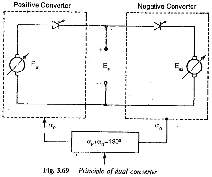
Sometimes dual converter finds application where speed control and regenerative capability are available in both directions of rotation. It operates in the reverse direction. Such a converter can be realised by combining two 2 quadrant converters having different directions of current. A converter allowing operation in all the four quadrants is called a four quadrants converters. It is also called a dual or reversing converter. It provides control as well as regeneration in both directions of rotation, as shown in Fig. 3.69.
A dual converter can be realised by either an antiparallel connection of two 2 quadrant converters or a cross connection. Figures 3.70 (a) and 3.71 (a) show the two possible connections of 3-pulse controlled rectifiers. Depending upon the current direction, either converter I or converter II feeds the current to the dc motor.
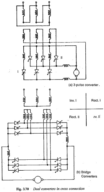
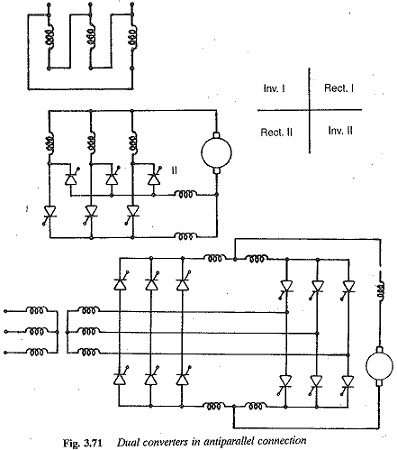
In an antiparallel connection a single secondary of the transformer is sufficient. The two converters operate in opposite directions as far as the dc load is concerned. On the other hand, a cross connection has individual secondaries for the converters. An antiparallel connection is advantageous with 3 pulse converters, whereas a cross connection is better with 6 pulse converters. Figure 3.70 (b) shows 6 pulse bridge converters supplying a reversible dc motor.
The block diagram of an antiparallel connection for a dual converter is depicted in Fig. 3.71(b). The firing angle of the two converters must be such that the average values of the voltages of the two converters are the same at the dc terminals, in both magnitude and polarity. Because of the nature of the connection this condition is possible only if one converter is a rectifier and the other an inverter. Thus, if αP is the firing angle of the converter operating as a rectifier (say positive group), the firing angle of the converter operating as an inverter (say negative group) αN = 180 — αP.
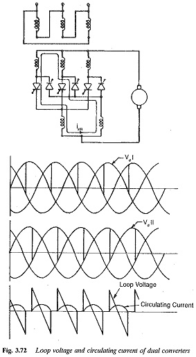
By controlling the firing angles of the converters, the average values of the voltages of the converters are made equal and of opposite polarity. Even though this condition is satisfied, the instantaneous values of the dc output voltages are not equal. The difference of these voltages, also called loop voltages, causes a circulating current. The circulating current is limited by the smoothing inductance. The path of the circulating current is shown in Fig. 3.72, for different firing angles. One can see that the current is continuous for α < 60° and becomes discontinuous for α > 60°. This is an additional loading on the thyristors and the transformer. However, it offers an advantage in that the circulating current does not permit the converter to go into discontinuous conduction and thus the associated difficulties are not present. The characteristics of the converter correspond to continuous conduction. The circulating current can be controlled. The control circuit adjusts the firing angles so that their sum is slightly less than 180°. This causes a difference in the average values, resulting in a dc component of the circulating current. This may reach unacceptable values if the difference of voltages is large and the limiting resistance and reactance are less.
Bridge circuits in an antiparallel connection forming a dual converter are shown in Fig. 3.71(b). This requires four current limiting reactors of large size and a circulating current having three pulses is established. This has a disadvantage with regard to its control circuit and hence is rarely used.
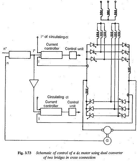
The cross connected converter in Fig. 3.70 (b) shows better behaviour. The circulating current has a sixth harmonic ripple. The average value of the circulating current and the smoothing inductance are smaller than in the case of three pulse circuits. The schematic of the control of a dc motor using cross connected bridges is shown in Fig. 3.73.
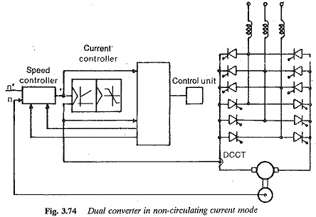
A dual converter can also be operated in a non-circulating current mode. The converter shown in Fig. 3.74 is made up of bridge converters in an antiparallel connection. The control logic should be such that at any instant only one converter conducts and the firing pulses to the other are blocked. The control circuit needs to be more sophisticated. The change over from one converter to the other takes place in the following way:
1.The sign change is provided at the output of the speed controller.
2.The speed controller is blocked by limiting the output voltage. The current controller is separated from the control circuit. The firing pulses are retarded to the inverter limit for the rapid building up of
3.The zero crossing of the current is detected and the pulses of the conducting converter are blocked.
4.The control circuit is again connected to the current controller. Control pulses to the converter and limiting of speed controller will be for the new direction of rotation.
There should be a time lag of 3 ms for change over to occur, because simultaneous conduction of the converters must be avoided. A single control circuit and one smoothing inductance are sufficient. The latter can be small in size, if the armature inductance is large. A transformer can be dispensed with if the supply voltage is employed directly. The control circuit needs further refinement in case discontinuous conduction takes place.