What is Series Compensation in Power System?:
Series Compensation – A capacitor in series with a line gives control over the effective reactance between line ends. This effective reactance is given by
![]()
where
- Xl = line reactance
- XC = capacitor reactance
It is easy to see that capacitor reduces the effective line reactance. This results in improvement in performance of the system as below.
- Voltage drop in the line reduces (gets compensated) i.e. minimization of end-voltage variations.
- Prevents voltage collapse.
- Steady-state power transfer increases; it is inversely proportional to X′l..
- As a result of (2) transient stability limit increases.
The benefits of the series capacitor compensator are associated with a problem. The capacitive reactance XC forms a series resonant circuit with the total series reactance
![]()
The natural frequency of oscillation of this circuit is given by
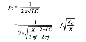
Where
- f = system frequency
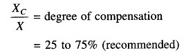
For this degree of compensation
![]()
which is subharmonic oscillation.
Even though series compensation has often been found to be cost-effective compared to shunt compensation, but sustained oscillations below the fundamental system frequency can cause the phenomenon, referred to as sub synchronous resonance (SSR) first observed in 1937, but got world-wide attention only in the 1970s, after two turbine-generator shaft failures occurred at the Majave Generating station in Southern Nevada. Theoretical studies pointed out that interaction between a series capacitor-compensated line, oscillating at subharmonic frequency, and torsional mechanical oscillation of turbine-generator set can result in negative damping with consequent mutual reinforcement of the two oscillations. Sub synchronous resonance is often not a major problem, and low cost countermeasures and protective measures can be applied.
Some of the corrective measures are:
- Detecting the low levels of subharmonic currents on the line by use of sensitive relays, which at a certain level of currents triggers the action to bypass the series capacitors.
- Modulation of generator field current to provide increased positive damping at subharmonic frequency.
Series inductors are needed for line compensation under light load conditions to counter the excessive voltage rise (Ferranti effect).
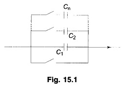
As the line load and, in particular the reactive power flow over the line varies, there is need to vary the compensation for an acceptable voltage profile. The mechanical switching arrangement for adjusting the capacitance of the capacitor bank in series with the line is shown in Fig. 15.1. Capacitance is varied by opening the switches of individual capacitances with the capacitance C1, being started by a bypass switch. This is a step-wise arrangement. The whole bank can also be bypassed by the starting switch under any emergent conditions on the line. As the switches in series with capacitor are current carrying suitable circuit breaking arrangement are necessary. However, breaker switched capacitors in series are generally avoided these days the capacitor is either fixed or thyristor switched.
With fast advancement in thyristor devices and associated switching control technology, the capacitance of the series capacitance bank can be controlled much more effectively; both stepwise and smooth control. This is demonstrated by the schematic diagram of Fig. 15.2 wherein the capacitor is shunted by two thyristors in antiparallel. Upon firing the thyristors alternately one carries current in positive half cycle and the other in negative half cycle.
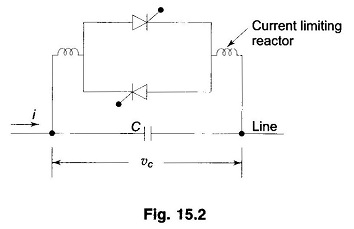
In each half cycle when the thyristor is fired (at an adjustable angle), it conducts current for the rest of the half cycle till natural current zero. During the off-time of the thyristor current is conducted by the capacitor and capacitor voltage is νc. During on-time of the thyristor capacitor is short circuited i.e. νc = 0 and current is conducted by the thyristor. The same process is repeated in the other half cycle. This means that νc can be controlled for any given i, which is equivalent of reducing the capacitance as C = νc/i. By this scheme capacitance can be controlled smoothly by adjusting the firing angle.
Thyristors are now available to carry large current and to withstand (during off-time) large voltage encountered in power systems. The latest device called a Gate Turn Off (GTO) thyristor has the capability that by suitable firing circuit, angle (time) at which it goes on and off can both be controlled.
This means wider range and finer control over capacitance. Similarly control is possible over series reactor in the line.
All controlled and uncontrolled (fixed) series compensators require a protective arrangement. Protection can be provided externally either by voltage arrester or other voltage limiting device or an approximate bypass switch arrangement. In no case the VI rating of the thyristors should be exceeded.
Depending on (i) kind of solid-state device to be used (ii) capacitor and/or reactor compensation and (iii) switched (step-wise) or smooth (stepless) control, several compensation schemes have been devised and are in use.
Some of the more common compensation schemes are as under.
- Thyristor Controlled Series Capacitor (TCSC)
- Thyristor Switched Series Capacitor (TSSC)
- Thyristor Controlled Reactor with Fixed Capacitor (TCR + FC)
- GTO thyristor Controlled Series Capacitor (GCSC)
- Thyristor Controlled reactor (TCR)
Capacitor and/or reactor series compensator act to modify line impedance. An alternative approach is to introduce a controllable voltage source in series with the line. This scheme is known as static synchronous series compensator (SSSC). SSSC has the capability to induce both capacitive and inductive voltage in series with line, thereby widening the operating region of the scheme. It can be used for power flow control both increasing or decreasing reactive flow on the line. Further this scheme gives better stability and is more effective in damping out electromechanical oscillations.
Though various types of compensators can provide highly effective power flow control, their operating characteristics and compensating features are different. These differences are related to their inherent attributes of their control circuits; also they exhibit different loss characteristics.
From the point of view of almost maintenance free operation impedance modifying (capacitors and/or reactors) schemes are superior. The specific kind of compensator to be employed is very much dependent on a particular application.