Principle Operation of Switching Power Converters:
Controllable reactive power can be generated by dc to ac switching converters which are switched in synchronism with the line voltage with which the reactive power is exchanged. A Switching Power Converters consists of an array of solid-state switches which connect the input terminals to the output terminals. It has no internal storage and so the instantaneous input and output power are equal. Further the input and output terminations are complementary, that is, if the input is terminated by a voltage source (charged capacitor or battery), output is a current source (which means a voltage source having an inductive impedance) and vice versa. Thus, the converter can be voltage sourced (shunted by a capacitor or battery) or current sourced (shunted by an inductor).
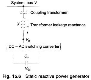
Single line diagram of the basic voltage sourced converter scheme for reactive power generation is drawn in Fig. 15.6. For reactive power flow bus voltage V and converter terminal voltage V0 are in phase.
Then on per phase basis
![]()
The reactive power exchange is

The switching circuit is capable of adjusting V0, the output voltage of the converter. For V0 < V, I lags V and Q drawn from the bus is inductive, while for V0 > V, I leads V and Q drawn from the bus is leading. Reactive power drawn can be easily and smoothly varied by adjusting V0 by changing the on-time of the solid-state switches. It is to be noted that transformer leakage reactance is quite small (0.1-0.15 pu), which means that a small difference of voltage (V-V0) causes the required I and Q flow. Thus the converter acts like a static synchronous condenser (or var generator).
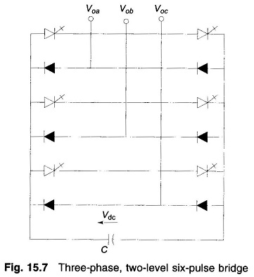
A typical converter circuit is shown in Fig. 15.7. It is a 3-phase two-level, six-pulse H-bridge with a diode in antiparallel to each of the six thyristors (Normally, GTO’s are used). Timings of the triggering pulses are in synchronism with the bus voltage waves.
As the converter draws only reactive power, the real power drawn from the capacitor is zero. Also at dc (zero frequency) the capacitor does not supply any reactive power. Therefore, the capacitor voltage does not change and the capacitor establishes only a voltage level for the converter. The switching causes the converter to interconnect the 3-phase lines so that reactive current can flow between them.
The converter draws a small amount of real power to provide for the internal loss (in switching). If it is required to feed real power to the bus, the capacitor is replaced by a storage battery. For this the circuit switching has to be modified to create a phase difference δ between V0 and V with V0 leading V.
The above explained converter is connected in shunt with the line. On similar lines a converter can be constructed with its terminals in series with the line. It has to carry the line current and provide a suitable magnitude (may also be phase) voltage in series with the line. In such a connection it would act as an impedance modifier of the line.