Regulated and Switching Power Supplies Interview Questions and Answers:
1. What is a regulated power supply?
Ans. A regulated power supply is an electronic circuit designed to provide constant dc voltage of predetermined value across load terminals, which is independent of variations in load current, ac mains voltage and temperature.
2. What is practical importance of voltage regulation in power supply?
Ans. Since the output voltage available from an unregulated power supply varies with the variations in load current, ac mains voltage and temperature and variations in dc output voltage may cause inaccurate or erratic operation or malfunctioning of many electronic circuits. Unregulated power supply is not considered suitable for many of the applications in electronics. That is why voltage regulation is of utmost importance in power supplies.
3. What is a regulated power supply and what are its parts?
Ans. A transformer, a rectifier circuit, a filter circuit, a voltage regulator along with some current limiting arrangement constitute a regulated voltage supply.
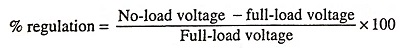
4. What is voltage regulation?
Ans. The variation of dc output voltage as a function of dc load current is called regulation. Percentage regulation is given as
For an ideal voltage regulator, output voltage should be independent of load current and the percentage regulation should be equal to zero.
5. What do you mean by the parameter ‘load regulation’?
Ans. The load regulation is the change in regulated output voltage when the load current changes from minimum to maximum value i.e.,
Load regulation, LR = No-load voltage, VNL – Full-load voltage VFL.
It is usually expressed in percentage and is given as

6. Define line and load regulation.
Ans. The source or line regulation is defined as the change in regulated output voltage for a specified range of line voltage, typically 230 V ± 10%.
The defining equation is
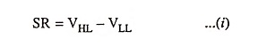
where VHL is output voltage with high input ac line voltage and VLL is output voltage with low input ac line voltage.
The percentage of source regulation is given as
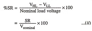
The output voltage under specific operating conditions is known as the nominal load (or output) voltage.
7. What is the function of a voltage regulator?
Ans. The primary function of a voltage regulator is to maintain a dc output voltage constant regardless of variations in load current or ac mains voltage.
8. What are the limitations of a regulator using zener diodes?
Ans. The efficiency of zener regulated power supply becomes very low when the load current is high. The other drawback is the shift in breakdown voltage due to change in temperature unless suitable compensation techniques are not used, the reference voltage level will shift according to temperature and this may affect the voltage regulation.
9. Why pass-transistor is so called?
Ans. Collector and emitter terminals of a transistor connected in a transistor series voltage regulator are in series with the load and whole load current pass through it, so it is called a pass-transistor.
10. Why emitter follower regulator is better than zener regulator?
Ans. The advantage of an emitter follower regulator is that the changes in zener current are reduced by a factor β and thus the effect of zener effect is largely reduced and much more stabilized output is obtained.
11. What is the need of foldback current limiting?
Ans. A problem with the simple current limiting, provided for protection against overload/short circuit, is that a large amount of power is dissipated in the series-pass resistor while the regulator remains short circuited. The foldback current limiting is the solution of this problem.
12. What is meant by ‘dropout’ voltage of an IC voltage regulator?
Ans. The dropout voltage, typically 2 V, is the minimum amount of voltage across the input-output terminals that is required to be maintained if the IC is to operate as a regulator.
13. What is the function of error amplifier in IC voltage regulator?
Ans. An error amplifier is essentially an op-amp with extremely high open-loop voltage gain. Because of high gain of an op-amp, the error voltage between the two input terminals approaches zero.
14. Why are series regulators called linear voltage regulators?
Ans. Series regulators are called linear voltage regulators because the pass-transistor used in such regulators operate in the active region (linear portion of its output characteristic).
15. What are the limitations of transistorized power supplies?
Ans. The stabilized voltage that can be obtained from transis-torized power supplies is limited to about 30 – 40 V only, because maximum safe value of VCE is about 50 V. This puts a limit to the use of transistorized power supplies.
16. What are the limitations of linear voltage regulators?
Ans. The main drawback of linear voltage regulator is the power dissipation in the pass-transistor which is operated in its linear mode. Other drawbacks of linear voltage regulators are that regulated power supplies using these regulators require a step-down transformer (most expensive and bulky component of the power supply) and large sized filter capacitors to reduce the ripple.
17. What are adjustable voltage regulators?
Ans. A voltage regulator is a circuit that supplies a constant voltage regardless of variation in load current or ac mains voltage. Sometimes variable voltage is required and under such a situation adjustable voltage regulator is used.
18. What are advantages of adjustable voltage regulators over fixed voltage regulators?
Ans. The adjustable voltage regulators offer variety of performance and reliability advantages over fixed voltage regulators i.e., improved system performance by having line and load regulation of a factor of 10 or better. Also it improves the system reliability and performance.
19. What is switching regulator? List the four major components of the switching regulator.
Ans. A switching regulator can be thought of as a similar to a linear regulator, but with the series-pass transistor operating as a switch that is either off or switched-on (in a saturated state). The output voltage from the switch is in a pulse waveform which is smoothed into a dc voltage by the action of an LC filter.
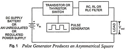
A basic switching regulator consists of four major components—voltage source, transistor (or thyristor) switch, pulse generator and a filter. The block diagram of a basic switching regulator is shown in Fig. 1.
Pulse generator produces an symmetrical square wave varying in either frequency or pulse width known as frequency modulation (FM) or pulse width modulation PWM) respectively. The pulse generator output alternately turns the switch on and off. Filter converts the pulse waveform from the output of the switch into a dc voltage. The basic filters are RC, RL or RLC, the RLC filter is the most commonly used.
20. What is the working principle of switching regulator?
Ans. Block diagram of a switching regulator is shown in Fig. 2. A switching regulator operates by chopping the unregulated de supply using a saturated transistor switch and then filtering the chopped voltage. By varying the duty cycle of the transistor, the output voltage can be regulated.
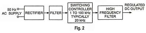
The switching regulator can often operate directly off the ac line. Therefore, the 50 Hz step-down transformer used in the series pass regulator is eliminated. In its place, a smaller and lighter high-frequency ferrite core transformer is used to transform the chopped dc voltage.
In switching regulators, a series pass transistor is used as a controlled switch and is operated either in cutoff region or saturation region which makes the power transfer via the pass transistor in the form of discrete pulses. SMPS utilizes pulse width modulation to control the average value of output voltage. The output is filtered through a low-pass L-C filter to produce an average dc output voltage. The output of L-C filter is a dc voltage with only a small ripple.
21. Define SMPS.
Ans. A switching regulator can be thought of as a similar to a linear regulator, but with the series-pass transistor operating as a switch that is either off or switched-on (in a saturated state). The output voltage from the switch is in a pulse waveform which is smoothed into a dc voltage by the action of an LC filter.
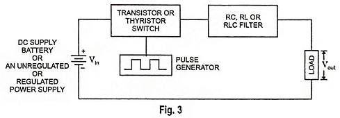
A basic switching regulator consists of four major components—voltage source, transistor (or thyristor) switch, pulse generator and a filter. The block diagram of a basic switching regulator is shown in Fig. 3.
Pulse generator produces an symmetrical square-wave varying in either frequency or pulse width known as frequency modulation (FM) or pulse width modulation (PWM) respectively. The pulse generator output alternately turns the switch on and off. Filter converts the pulse waveform from the output of the switch into a dc voltage. The basic filters are RC, RL or RLC, the RLC filter is the most commonly used.
22. Given the difference between an electronic generator and off-line UPS.
Ans. An electronic generator is the same as the off-line UPS system except for one difference that switching time from the mains supply to battery driven inverter supply will not be small (over 10 ms) for the electronic generator. Also, the electronic generators will run for longer time (1 to 4 hours) than off-line UPS systems because, usually large size lead-acid batteries are used with electronic generators.
23. The demand for on-line UPS system is less than for off-line UPS system. Why?
Ans. The demand for on-line UPS system is less than for off-line UPS system because the former is costlier one.