Smoothing Circuits:
The rectified a.c. consists of a series of undirectional half waves of current or voltage. It is generally desirable to smooth this output. The various filters used for Smoothing Circuits are the conventional RC filter, RC chain filter, transistorized filter, bucking transformer filter, phase splitting circuits, etc., some basic Smoothing Circuits are shown in Fig. (10.24).
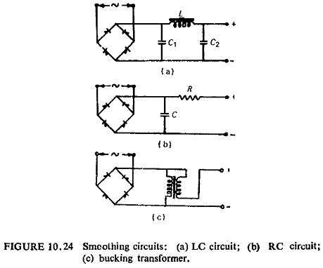
In the bucking transformer filter a transformer is used to cancel out the a.c. component. This method is not suitable where the input is limited because the primary winding provides a low resistance shunt path for the d.c. diverting it from the output.
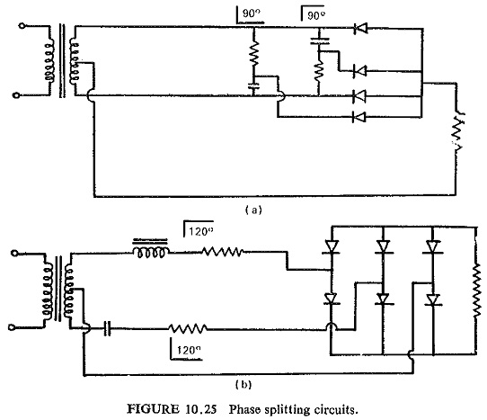
If the speed requirement is not too stringent the conventional capacitor filters could be used. A faster method is phase splitting before rectification where the input single phase quantity is split into a multi phase system and thus greatly reduces the harmonic currents after smoothing (Fig. 10.25)).
Voltage Regulators:
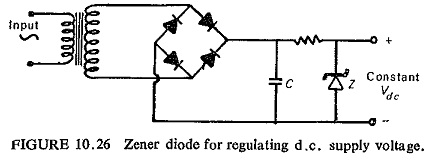
It has already been pointed out that many diodes are designed and constructed for operation on the breakdown (avalanche) portion of the characteristic curve. These diodes are known as zener diodes or reference diodes As is obvious from their characteristics they are used for holding a voltage constant over a wide range of applied voltage. A simple circuit is shown in Fig. (10.26).
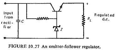
One or more transistors can be used in conjunction with the reference diode, however, to greatly increase the efficiency of the regulator by reducing the current through the reference diode. A typical circuit of this type is shown in Fig (10.27). This circuit is known as emitter-follower regulator because the output voltage follows the reference voltage. Filters are also introduced to reduce the ripple in the output wave.
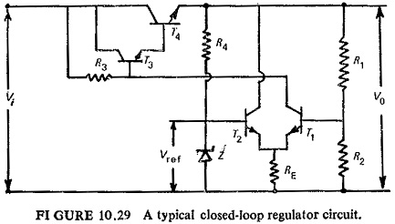
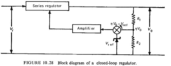
Although the emitter-follower regulators provide satisfactory performance for many applications their output resistance cannot be reduced below a particular limit, large value of filter capacitance (CF) are required to provide very low values of ripple. On the other hand, regulators that employ the principle of negative feedback can provide almost any desired value of output resistance and ripple quite easily. The block diagram of a closed-loop regulator is shown in Fig (10.28). A fraction of the output voltage ηV0 is compared with the reference voltage Vref, and their difference is amplified and used to control the series regulator, which in turn controls the output voltage.
A typical circuit diagram that will perform this basic function is shown in Fig. (10.29). The differential amplifier consisting of T1 and T2 provides both the voltage comparison and the amplification functions.