Voltage Doubler Circuits:
Both full wave and half wave rectifier circuits produce a d.c. voltage less than the a.c. maximum voltage. When higher d.c voltages are needed, a Voltage Doubler Circuits or cascaded rectifier doubler circuits are used. The schematic diagram of voltage doublers are given in Figs 6.3a and b.
In Voltage Doubler Circuits shown in Fig. 6.3a, the capacitor C1 is charged through rectifier R1 to a voltage of +Vmax with polarity as shown in the figure during the negative half cycle. As the voltage of the transformer rises to positive Vmax during the next half cycle, the potential of the other terminal of C1 rises to a voltage of +2Vmax.
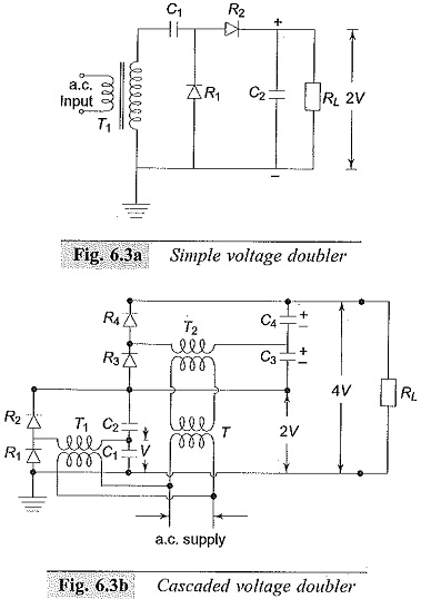
Thus, the capacitor C2 in turn is charged through R2 to 2Vmax. Normally the d.c. output voltage on load will be less than 2Vmax , depending on the time constant C2RL and the forward charging time constants. The ripple voltage of these circuits will be about 2% for RL/r ≤ 10 and X/r ≤ 0.25, where X and r are the reactance and resistance of the input transformer. The rectifiers are rated to a peak inverse voltage of 2Vmax, and the capacitors C1 and C2 must also have the same rating.

Cascaded voltage doublers are used when larger output voltages are needed without changing the input transformer voltage level. A typical voltage doubler is shown in Fig. 6.3b and its input and output waveforms are shown in Fig. 6.3c. The rectifiers R1 and R2 with transformer T1 and capacitors C1 and C2 produce an output voltage of 2 V in the same way as described above. This circuit is duplicated and connected in series or cascade to obtain a further voltage doubling to 4 V.
T is an isolating transformer to give an insulation for 2Vmax since the transformer T2 is at a potential of 2Vmax above the ground. The voltage distribution along the rectifier string R1,R2,R3 and R4 is made uniform by having capacitors C1,C2,C3 and C4 of equal values.
The arrangement may be extended to give 6 V, 8 V, and so on by repeating further stages with suitable isolating transformers. In all the voltage doubler circuits, if valves are used, the filament transformers have to be suitably designed and insulated, as all the cathodes will not be at the same potential from ground. The arrangement becomes cumbersome if more than 4 V is needed with cascaded steps.