Mathematical Model of Lightning Stroke:
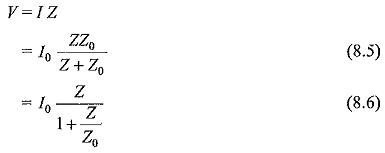
During the charge formation process, the cloud may be considered to be a nonconductor. Hence, various potentials may be assumed at different parts of the cloud. If the charging process is continued, it is probable that the gradient at certain parts of the charged region exceeds the breakdown strength of the air or moist air in the cloud. Hence, local breakdown takes place within the cloud. This local discharge may finally lead to a situation wherein a large reservoir of charges involving a considerable mass of cloud hangs over the ground, with the air between the cloud and the ground as a dielectric. When a streamer discharge occurs to ground by first a leader stroke, followed by main strokes with considerable currents flowing, the Mathematical Model of Lightning Stroke may be thought to be a current source of value I0 with a source impedance Z0 discharging to earth. If the stroke strikes an object of impedance Z, the voltage built across it may be taken as
The source impedance of the lightning channels are not known exactly, but it is estimated to be about 1000 to 3000 Ω. The objects of interest to electrical engineers, namely, transmission line, etc. have surge impedances less than 500 Ω (overhead lines 300 to 500 Ω, ground wires 100 to 150 Ω, towers 10 to 50 Ω, etc.). Therefore, the value Z/Z0 will usually be less than 0.1 and hence can be neglected. Hence, the voltage rise of lines, etc. may be taken to be approximately V = I0Z, where I0 is the Mathematical Model of Lightning Stroke current and Z the line surge impedance.
If a Mathematical Model of Lightning Stroke current as low as 10,000 A strikes a line of 400 Ω surge impedance, it may cause an overvoltage of 4000 kV. This is a heavy overvoltage and causes immediate flashover of the line conductor through its insulator strings.
In case a direct stroke occurs over the top of an unshielded transmission line, the current wave tries to divide into two branches and travel on either side of the line. Hence, the effective surge impedance of the line as seen by the wave is Z0/2 and taking the above example, the overvoltage caused may be only 10,000 (400/2) = 2000 kV. If this line were to be a 132 kV line with an eleven 10 inch disc insulator string, the flashover of the insulator string will take place, as the impulse flashover voltage of the string is about 950 kV for a 2 μs front impulse wave.
The incidence of lightning strikes on transmission lines and sub-stations is related to the degree of thunderstorm activity. It is based on the level of “Thunderstorm days” (TD) known as “Isokeraunic Level” defined as the number of days in a year when thunder is heard or recorded in a particular location. But this indication does not often distinguish between the ground strokes and the cloud-to-cloud strokes. If a measure of ground flashover density (Ng) is obtained, then the number of ground flashovers can be computed from the TD level. From the past records and the past experience, it is found that![]()
It is reported that TD is between 5 and 15 in Britain, Europe and Pacific west of North America, and is in the range of 30 to 50 in Central and Eastern states of U.S.A. A much higher level is reported from South Africa and South America. No literature is available for the different regions in India, but a value of 30 to 50 may be taken for the coastal areas and for the central parts of India.
Model for Lightning Stroke Effect and Computation of Induced Voltages:
In lightning studies, the strokes to ground are of importance as they induce over-voltages on transmission lines and in nearby objects. Hence, a model based on lightning return stroke is presented here which assumes that the lightning channel is straight, vertical and normal to the ground plane. The return stroke current I (Z, t) is assumed as function of vertical co-ordinate z and time t and the initial current I (o, t) is of importance in engineering applications. The electromagnetic fields associated with the lightning current and the lightning induced voltages are calculated based on the return stroke current equations taken as
where, ν is the return stroke velocity assuming that the current pulse propagates without attenuation and distortion in the upward channel. Since the current varies both in space and time, the electric field and magnetic field associated with it can be calculated using Maxwell’s equations for time varying fields.
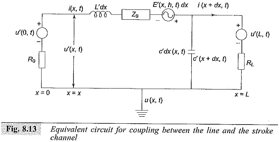
Whenever a transmission line is nearer to the stroke channel there will be a coupling between the line and the stroke channel. The total voltage induced on the line, is computed by solving the coupling equations involving the total induced voltage u (x, t) and the induced current i (x, t) assuming that the transmission line is in the directions. An equivalent circuit for coupling is given by Agrawal et al (Fig. 8.13) from which the voltage at any length x = L can be computed.
Where
L = length of line,
R0,R1 = terminating resistance
L′,C = inductance and capacitance of line per unit length (dynamic)
u’ (x,t) = voltage developed at any distance x
i’ (x,t) = current through the line at any distance x
E’ (x,h,t) = Electric field in x direction at a height h (transmission line height)
Zg = equivalent ground impedance.
The factors that influence the lightning induced voltages on transmission lines are
-
the ground conductivity,
-
the leader stroke current, and
-
corona.
The induced voltages based on the Agrawal model are modified taking into account these parameters. With computer analysis, the prediction of overvoltage on the transmission lines and lightning performance of the line, i.e. flashover rate of the line insulation, can be predicted accurately.


