Shunt Clipping Circuits:
A positive Shunt Clipping Circuits is illustrated in Fig. 3-28(a). Here the diode is connected in shunt (or parallel) with the output terminals. When the input is negative, the diode is reverse biased and only a small voltage drop occurs across RI, due to load current IL. This means that the circuit output voltage (Vo) is approximately equal to the negative input peak (-E). When the input is +E, D1 is forward biased, and the output voltage equals the diode voltage drop (+VF). Thus, the positive half of the waveform is clipped off. As illustrated, the upper and lower levels of the output of a positive shunt clipper are approximately +VF and -E.
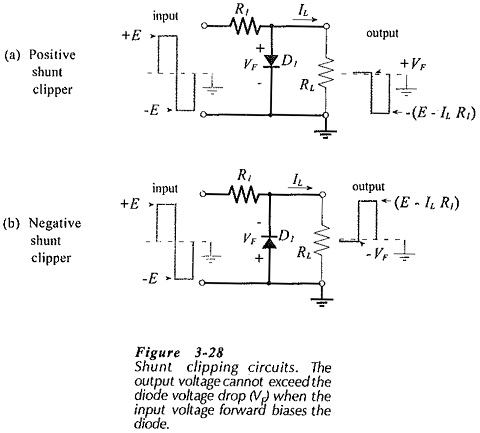
A negative Shunt Clipping Circuits is exactly the same as a positive shunt clipper with the diode polarity reversed, [see Fig. 3-28(b)]. The negative half-cycle of the waveform is clipped off.
The load current on a shunt clipper produces a voltage drop (IL R1) across the resistor, which might be insignificant where the load current is very low.![]()
As in the case of series clipping circuits, Shunt Clipping Circuits may be used with square, sinusoidal, or other input waveforms.
Shunt Noise Clipper:
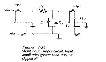
The shunt noise clipper shown in Fig. 3-30 removes noise riding on the peaks of an input waveform. The signal amplitude must be greater than the diode forward voltage drop. The output waveform is clipped, at ±VF , so that the noise is not passed to the output. This type of clipper is used with pulse signals, where the pulse amplitude is not important. In this case, information is contained in the pulse width, or simply in its presence or absence.
Biased Shunt Clipper:
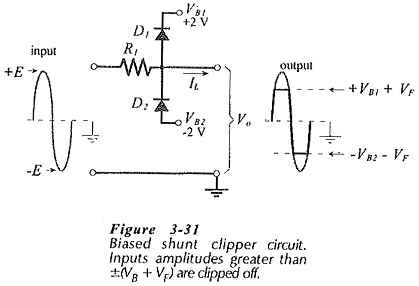
Figure 3-31 shows a clipping circuit that uses two diodes which have different bias voltages. The cathode of D1 is connected to a +2 V bias (VB1), and the anode of D2 has a -2 V bias (VB2). While the input waveform amplitude is less than ±(VB + VF), neither diode is forward biased, and the input is simply passed to the output. When the positive input is greater than (VB1 + VF). D1 becomes forward biased, and the output cannot exceed this voltage. Similarly, when the negative input goes below (-VB2 – VF). D2 is forward biased, and the output is limited to -(VB2 + VF).
![]()
For obvious reasons, the circuit is termed a biased Shunt Clipping Circuits. Biased shunt clippers are used to protect circuits or devices from (positive/negative) input voltages that must not exceed specified levels.
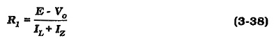
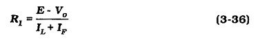
The voltage across resistor R1 is (E – Vo), and the resistor current is the sum of the load current and the diode forward current (IL + IF). As in other diode circuits, a minimum level of IF is selected, and the resistor value is calculated as,
Zener Diode Shunt Clipper:
A Zener diode shunt clipper produces the same kind of result as a biased shunt clipper without the need for bias voltages. The clipper circuit in Fig. 3-32 has two back-to-back series-connected Zener diodes.
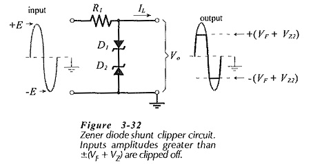
When the input voltage is positive and has sufficient amplitude, D1 is forward bias and D2 is biased into reverse breakdown. At this time, the output voltage is limited to (VF + VZ2). A negative input voltage produces a maximum negative output of -(VF + VZ1). With equal-voltage Zener diodes, the maximum output voltage is,
![]()
The resistor voltage is (E – Vo), and the resistor current is (IL + IZ). A minimum level of IZ (greater than the device knee current) is selected, and the resistor value is calculated as,